FG4 Multibox Manual
Document version: 7.0
Firmware version: 7.0
Document version: 7.0
Firmware version: 7.0
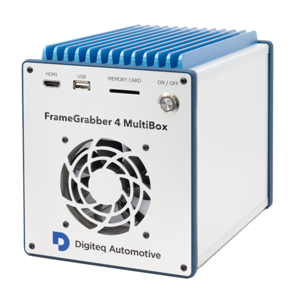
FG4 Multibox (aka. MGB4) is a device, whose primary purpose is capturing/generating video streams from/to specific hardware interfaces. For this the box uses FG4 PCIe cards, each one equipped with appropriate interface module (e.g. FPD-Link, GMSL). Both FG4 Multibox and FG4 PCIe cards are products of Digiteq Automotive.
System on Module (SOM) provides the main computing power. Currently Nvidia Jetson TX2 or TX2i is used as SOM. It contains Dual-Core Nvidia Denver 2 and Quad-Core ARM Cortex-A57 CPUs, 256-core Nvidia Pascal GPU, 8GB LPDDR4 RAM and 32GB eMMC storage. It also contains many peripherals, but not all are used or they are used in specific configuration.
Mainboard interconnects all participated electronic components into one functional unit. Except connectors it also contains many other active elements, like power supply, power management IC (PMIC), RTC battery, CAN drivers, etc. Especially the PMIC is very important, as it controls the onboard power supply, power on/off sequences and also external triggers. It also provides the ability to automatically power-on the FG4 Multibox, either when it gets connected to power supply or when configured events occur on external triggers.
PCIe switch board expands the Nvidia Jetson TX2/TX2i single PCIe 2.0 x4 interface and allows to use up to five PCIe cards.
FG4 Multibox is Linux based device. The behavior of all subsystems (e.g. system time, video, network, CAN), the way of connecting storage devices or handling system logs, all that stuff is Linux based and this fact is clearly reflected in behavior of API. So it is quite common, that the API provided by FG4 Multibox noticeably resembles the API provided by underlying Linux operating system. Also the behavior of internal services (e.g. http server, ntp client, secure shell), the list of supported features (e.g. file systems) or the list of supported external devices (e.g. CAN or network cards) are all closely dependent on used Linux distribution and kernel.
Used Linux distribution:
Customized Ubuntu 18.04 (Bionic Beaver)
Used Linux kernel:
GNU/Linux 4.9.201-mgb4 aarch64, customized kernel based on Nvidia Tegra Linux, tag tegra-l4t-32.5
Although there are running many Linux services, only a few of them expose their API and also form the core FG4 Multibox functionality.
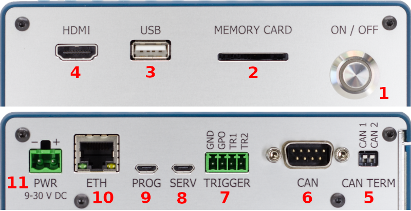
Short press of the power button triggers the FG4 Multibox power-on or power-off sequences. Power-off sequence may also be triggered by API. Power-on sequence may also be triggered automatically by Mainboard PMIC. There exist more types of power sequences and they all may be trigger only by API. The progress of power sequences is indicated by Power button LED.
Power button LED indicates some significant states of FG4 Multibox.
Full-size SD card interface supporting up to SDR104 card mode (UHS-1). Working with storage devices is described in Storage chapter.
USB 2.0, Type-A, Host mode. Multiple device types may be connected via USB interface. See Storage, Network or CAN chapters to get detailed information about working with these devices.
HDMI 2.0, Type A (standard) or C (mini), depending on particular FG4 Multibox hardware revision. The interface is intended for connecting external display, where an useful content may be shown. See Screen chapter to get detailed information about connected display. See GUI chapter to get information about shown content.
DIP switches, that allow to connect internal termination resistors to embedded CAN buses 1 and 2. When the switch is in position ON (pulled down), internal rezistor 120Ω is connected between CAN high (CANH) and CAN low (CANL) signals.
Standard 9-pin CANON male connector, that provides access to embedded CAN buses 1 and 2. The physical layer complies with high-speed CAN (HS-CAN) as defined in ISO 11898-2:2016 and SAE J2284-1 to SAE J2284-5.
| 1 | - not connected |
| 2 | - CAN low (CAN bus 1) |
| 3 | - CAN GND |
| 4 | - CAN low (CAN bus 2) |
| 5 | - not connected |
| 6 | - not connected |
| 7 | - CAN high (CAN bus 1) |
| 8 | - CAN high (CAN bus 2) |
| 9 | - not connected |
FG4 Multibox contains four embedded CAN devices connected to these CAN buses.
The first two CAN devices are located on System on Module (SOM). They can be configured via API, where they are named as jcan1 (connected to the CAN bus 1) and jcan2 (connected to the CAN bus 2). These devices provide the possibility to capture the CAN traffic.
The second two devices are located on Mainboard PMIC. They can be configured via API, where they are named as can1 (connected to the CAN bus 1) and can2 (connected to the CAN bus 2). These devices provide the possibility to wake-up the FG4 Multibox on reception of specific CAN message.
External triggers TR1 and TR2 are hardware inputs, that can be used to trigger various events within the FG4 Multibox. The inputs are directly connected to Mainboard PMIC, so their properties can also be set via Mainboard PMIC, e.g. connecting pull-up or pull-down resistors, setting the specific triggering edge etc. They are part of Trigger system, so the mapping of events can also be set via Trigger system, e.g. capturing the video frame, rendering the specific trigger mark in video frame etc.
Connector type: DEGSON 15EDGK-3.5-04P-14
| Low level input voltage | : <0.8V |
| High level input voltage | : >2.0V |
| Maximum input voltage | : ±35.0V |
| Internal pull-up/down resistors | : 40-130kΩ |
| Input current (no pull-up/down) | : 3-180nA@3.3V |
USB 2.0, Micro-B, Device mode (FTDI, FT232R USB UART, idVendor=0403, idProduct=6001), 115200 8n1. This serial device provides access to the FG4 Multibox U-boot and Linux console.
USB 2.0, Micro-B, Device mode (NVIDIA Corp., APX, idVendor=0955, idProduct=7c18). This device is provided by Nvidia Jetson TX2/TX2i SOM booted in recovery mode. The interface is intended only for Digiteq Automotive factory programming of FG4 Multibox.
Ethernet 10/100/1000 BASE-T, RJ45. Working with network devices is described in Network chapter. This network device is named as jeth0 in API.
| Input voltage | : 10-30V DC | |
| Idle current | : 20mA@12V | | Power-off state |
| Estimated max. power | : (20 + 15n) W | | Heavy computing load |
| Estimated min. power | : (13 + 10n) W | | No computing load |
where
n - number of inserted FG4 PCIe cards
E.g.
When only one FG4 PCIe card is inserted, power supply 12V/3A should be enough.
When five FG4 PCIe cards are inserted, power supply 12V/8A should be enough.
Connector type: DEGSON 2EDGK-5.0-02P-14
Next chapters describe the non-gui application interface, intended to be used directly from programming languages, e.g. some automation tools or gui applications. Web application providing the GUI also uses this API as its backend. Please, read the Services chapter first, as this describes the API fundamental behavior and also defines the terms, that are used by all following API related chapters.
Many chapters contain examples, that show how to communicate with API from OS shell by using some commonly available tools (curl, nc, wscat, ...). These examples are written for Linux Bash, so they may be copy-pasted into this shell directly. When using other shells (e.g. Windows cmd), some modifications may be required.
Most of the FG4 Multibox functionality is executed by its internal sotware services, each one with its special purpose. Some of these services expose their API, so they can be controlled by user. The API is exposed in different ways, e.g. each video stream is available on its dedicated TCP server, file sharing is done through Samba server, but the most functionality is available through HTTP server.
The most important services are:
They all expose their API and also form the core functionality of FG4 Multibox.
HTTP server listens on TCP port 80.
Samba server listens on TCP ports 139 and 445.
NTP server listens (if enabled) on UDP port 123.
Dedicated TCP servers (e.g. video stream servers) have no fixed listening TCP ports, as they are configurable by user.
No username or password is required.
This is the most important service as this one is responsible for control over the biggest part of the whole system, e.g. setting video, network and CAN interfaces, mounting storage drives etc.
Most of the functionality is available through HTTP server at URL path /api/app/*. The service also provides dedicated TCP servers (e.g. video stream servers). Next description refers only to communication through HTTP server.
The service functions may take or return some data. In this case, data are always passed in message body as a single JSON object. For information about JSON object see RFC8259.
The service uses the same status codes for all its functions, 200 (ok) or 202 (accepted) for success, whatever else for a kind of error. The service itself uses only 400 (bad request), 422 (unprocessable entity) and 500 (internal server error), but another error status codes may be returned if transaction fails somewhere on its route, e.g. 502 (bad gateway). In case of error, the service may return detailed error description in output data, JSON schema is available here. Status codes 202 (accepted) and 422 (unprocessable entity) are used only by actions.
The service can be viewed as hierarchy of functional objects, each one responsible for specific part of the system. Each object has its own invokable actions, readable and writable configuration properties and readable status properties. Mainly due to this characteristics the API is divided into separated parts.
This part of API allows the object to perform an immediate activity, this is done by invoking its action. Actions are available at URL path /api/app/actions/*. The list of currently available (at runtime) actions can be obtained by GET verb at URL path /api/app/actions. The list of all existing actions, including JSON schemas of input and output data, is available here. There exist two types of actions, synchronous and asynchronous.
Synchronous action finishes immediately. It is invoked by POST verb on required action name and the result is returned in response. Status code 200 (ok) means, that the action finished with success (output data are present in response), status code 422 (unprocessable entity) means, that the action finished with error, another status code means another kind of error (action failed in some unexpected way or didn't be even started).
Asynchronous action takes some time to finish, so the result is not available immediately, instead it must be polled later. Action is invoked by POST verb on required action name. Status code 202 (accepted) means, that the action was started (but not finished), another status code means a kind of error. Result is obtained by GET verb on the same action name. Status code 202 (accepted) means, that the action has not finished yet, status code 200 (ok) means, that the action finished with success (output data are present in response), status code 422 (unprocessable entity) means, that the action finished with error, another status code means another kind of error.
List available actions
curl -v -X GET 'http://192.168.1.200/api/app/actions'Get system time
curl -v -X POST 'http://192.168.1.200/api/app/actions/time/system_time/get'Echo some JSON data
curl -v -X POST -H 'Content-Type: application/json' -d '"hello"' 'http://192.168.1.200/api/app/actions/echo'This part of API allows to set the object into required state, this is done by setting its configuration properties. Configuration is available at URL path /api/app/config and corresponding JSON schema is available here. It is possible to address only part of configuration, which is done by specifying the appropriate JSON pointer in URL path (/api/app/config<json_pointer>, /api/app/config/point/to/something). For information about JSON pointer see RFC6901. There are several HTTP verbs, than can be used on configuration and that are similar to known CRUD operations:
GET - reads existing configuration. Optional JSON pointer in URL path must point to existing object. Output data in message body. No input data.
PUT - updates (by replacing) existing configuration. Optional JSON pointer in URL path must point to existing object. Input data in message body. No output data.
PATCH - updates (by patching) existing configuration. Optional JSON pointer in URL path must point to existing object. Input data (JSON patch) in message body. No output data. For information about JSON patch see RFC6902
POST - creates new configuration. Required JSON pointer in URL path must meet some criteria to work properly. Let's have a pointer /x/y/z. In this case object pointed by /x/y must exist and /x/y/z will be created (if not exists yet) or replaced (if already exists). Input data in message body. No output data.
DELETE - deletes existing configuration. Required JSON pointer in URL path must meet some criteria to work properly. Let's have a pointer /x/y/z. In this case object pointed by /x/y must exist and /x/y/z will be deleted (if exists) or nothing will be done (if not exists). No input data. No output data.
When any method able to change the existing configuration fails, then the configuration remains in its previous state, no partial changes are made.
The provided configuration must always be valid against the currently supported version of schema. But there is one exception, that is called configuration import. It is allowed to provide configuration of lower version than currently supported. In this case the configuration is imported to the current version. Note that provided configuration of lower version still must be valid against its schema (of matching lower version).
It was mentioned, that provided configuration must always be valid against its schema. This is the first and fundamental check, that is performed with the received configuration. But there may be additional checks, especially in situations, that cannot be easily detected by schema. Currently there exists only one additional check, which doesn't allow to assign the same TCP port to multiple TCP servers.
Get configuration of the whole system
curl -v -X GET 'http://192.168.1.200/api/app/config'Check if NTP client is enabled
curl -v -X GET 'http://192.168.1.200/api/app/config/time/ntp/enabled'Enable NTP client
curl -v -X PUT -H 'Content-Type: application/json' -d 'true' 'http://192.168.1.200/api/app/config/time/ntp/enabled'Enable NTP client and trigger file writer
curl -v -X PATCH -H 'Content-Type: application/json' -d '{"time":{"ntp":{"enabled":true}},"trigger":{"file_writer":{"enabled":true}}}' 'http://192.168.1.200/api/app/config'This part of API allows to observe real state of the object, this is done by getting its status properties. Status is available at URL path /api/app/status and corresponding JSON schema is available here. It is possible to address only part of status, which is done by specifying the appropriate JSON pointer in URL path (/api/app/status<json_pointer>, /api/app/status/point/to/something). Getting status is done by GET verb.
Internally the status properties are updated with period of about 1 second. So it has no sense to get the status more often.
Get status of the whole system
curl -v -X GET 'http://192.168.1.200/api/app/status'Check if NTP client is really running
curl -v -X GET 'http://192.168.1.200/api/app/status/time/ntp/running'Get CPU info
curl -v -X GET 'http://192.168.1.200/api/app/status/cpu'This part of API allows to get all JSON schemas used by the service. Schemas are available at URL path /api/app/schemas. It is possible to address only part of schemas, which is done by specifying the appropriate JSON pointer in URL path (/api/app/schemas<json_pointer>, /api/app/schemas/point/to/something). Getting schemas is done by GET verb. There are four important parts.
/api/app/schemas/error - JSON schema of error (see here)
/api/app/schemas/actions - JSON schemas of actions data (see here)
/api/app/schemas/config - JSON schema of configuration (see here)
/api/app/schemas/status - JSON schema of status (see here)
Get all JSON schemas
curl -v -X GET 'http://192.168.1.200/api/app/schemas'Get JSON schema of error
curl -v -X GET 'http://192.168.1.200/api/app/schemas/error'Get JSON schema of configuration
curl -v -X GET 'http://192.168.1.200/api/app/schemas/config'This service provides access to system log. These may be useful to create a more detailed look at the whole system and possibly to help with some debugging.
The service is available through HTTP server at URL path /api/log/*.
The service uses the same status codes for all its functions, 200 (ok) for success, whatever else for a kind of error. The service itself uses only 400 (bad request) and 500 (internal server error), but another error status codes may be returned if transaction fails somewhere on its route, e.g. 502 (bad gateway).
The service uses the same websocket return codes for all its websocket functions, 1000 for success, whatever else for some kind of error. Reason string may be filled with detailed information.
The service uses the same form of passing parameters for all its functions. It uses the query string in pretty standard form, e.g. /api/log/file?what=app&count=10.
Log file can be downloaded by GET verb at URL path /api/log/file. Parameters may be specified to control the content of the log file.
what - identifies the log source. Possible values are all (all sources), kernel (kernel source) and app (application service source). Default value is all.
count - determines the number of required historical records to be sent. If equal -1, then all records are sent. Default value is -1.
since, until - sents only records on or newer than the specified date, or on or older than the specified date, respectively. Date specifications should be of the format YYYY-MM-DD HH:MM:SS. If the time part is omitted, 00:00:00 is assumed. If only the seconds component is omitted, :00 is assumed. If the date component is omitted, the current day is assumed. Alternatively the strings yesterday, today, tomorrow are understood, which refer to 00:00:00 of the day before the current day, the current day, or the day after the current day, respectively. now refers to the current time. Finally, relative times may be specified, prefixed with - or +, referring to times before or after the current time, respectively.
Get all records of the whole system
curl -v -X GET 'http://192.168.1.200/api/log/file'Get today's records of the whole system
curl -v -X GET 'http://192.168.1.200/api/log/file?since=today'Get last 10 records of application service
curl -v -X GET 'http://192.168.1.200/api/log/file?what=app&count=10'Live log can be received by connecting to websocket at URL path /api/log/feed. Parameters may be specified to control the content of the log data.
what - identifies the log source. Possible values are all (all sources), kernel (kernel source) and app (application service source). Default value is all.
count - determines the number of required historical records to be sent. If equal -1, then all records are sent. Default value is 10.
follow - determines the state of log feed after sending required count of historical records. If equal 0, then after sending required count of historical records the feed closes immediately. If equal 1, then after sending required count of historical records the feed remains open to provide future records. Default value is 1.
Connect to feed of the whole system (send 10 historical records before waiting for new records)
wscat --connect 'http://192.168.1.200/api/log/feed'Connect to feed of the whole system (send no historical records before waiting for new records)
wscat --connect 'http://192.168.1.200/api/log/feed?count=0'The whole log can be cleared by POST verb at URL path /api/log/clear.
Clear log
curl -v -X POST 'http://192.168.1.200/api/log/clear'This service provides access to available file systems. This means either mounted devices (e.g. internal hard disk drive, USB drive, SD card) or another specific places (e.g. directory for uploading new firmware).
The service is available through HTTP server at URL path /api/fs/*. In this case WebDAV is used to access the file system. When GET verb is used onto existing directory, then list (in JSON format) of files is returned. Both read and write operations may be possible.
The service is also available through HTTP server at URL path /www/fs/*. In this case the file system is presented as ordinary static web page, so only GET verb can be used. Only read operations are possible.
The service is also available through Samba server. Both read and write operations may be possible.
Currently mounted devices are available at URL paths /api/fs/mounts/ and /www/fs/mounts/ in case of using HTTP server, or at URL path /mounts/ in case of using Samba server. The top level content of these URL paths represents the storage mount points. See Storage chapter for detailed information about storage devices and their mount points.
There exists a special file system place, that is intended only for control of firmware update process. This place is available at URL paths /api/fs/fw/ and /www/fs/fw/ in case of using HTTP server, or at URL path /fw/ in case of using Samba server. See Firmware chapter for detailed information about firmware update.
Get list of mount points (via HTTP, WebDAV). Both variants are possible.
curl -X PROPFIND 'http://192.168.1.200/api/fs/mounts/'
curl -X GET 'http://192.168.1.200/api/fs/fw/'
Get content of firmware upload directory (via HTTP, WebDAV). Both variants are possible.
curl -X PROPFIND 'http://192.168.1.200/api/fs/fw/'
curl -X GET 'http://192.168.1.200/api/fs/fw/'
Get content of satadisk mount point directory (via HTTP, WebDAV). Both variants are possible.
curl -X PROPFIND 'http://192.168.1.200/api/fs/mounts/satadisk/'
curl -X GET 'http://192.168.1.200/api/fs/mounts/satadisk/'
Upload video.ts file to satadisk mount point directory (via HTTP, WebDAV)
curl -T video.ts 'http://192.168.1.200/api/fs/mounts/satadisk/video.ts'Download video.ts file from satadisk mount point directory (via HTTP, WebDAV)
curl -o file.ts 'http://192.168.1.200/api/fs/mounts/satadisk/video.ts'Delete video.ts file from satadisk mount point directory (via HTTP, WebDAV)
curl -X DELETE 'http://192.168.1.200/api/fs/mounts/satadisk/video.ts'Move/Rename video.ts file to video/video.ts file within the mount point satadisk (via HTTP, WebDAV). Directory video must already exist. Both variants are possible.
curl -X MOVE -H 'Destination:http://192.168.1.200/api/fs/mounts/satadisk/video/video.ts' 'http://192.168.1.200/api/fs/mounts/satadisk/video.ts'
curl -X MOVE -H 'Destination:/api/fs/mounts/satadisk/video/video.ts' 'http://192.168.1.200/api/fs/mounts/satadisk/video.ts'
Copy video.ts file to video/video.ts file within the mount point satadisk (via HTTP, WebDAV). Directory video must already exist. Both variants are possible.
curl -X COPY -H 'Destination:http://192.168.1.200/api/fs/mounts/satadisk/video/video.ts' 'http://192.168.1.200/api/fs/mounts/satadisk/video.ts'
curl -X COPY -H 'Destination:/api/fs/mounts/satadisk/video/video.ts' 'http://192.168.1.200/api/fs/mounts/satadisk/video.ts'
Create video directory in satadisk mount point directory (via HTTP, WebDAV)
curl -X MKCOL 'http://192.168.1.200/api/fs/mounts/satadisk/video/'Delete video directory from satadisk mount point directory (via HTTP, WebDAV)
curl -X DELETE 'http://192.168.1.200/api/fs/mounts/satadisk/video/'Move/Rename video directory to bar/video directory within the mount point satadisk (via HTTP, WebDAV). Directory bar must already exist. Both variants are possible.
curl -X MOVE -H 'Destination:http://192.168.1.200/api/fs/mounts/satadisk/foo/videos/' 'http://192.168.1.200/api/fs/mounts/satadisk/videos/'
curl -X MOVE -H 'Destination:/api/fs/mounts/satadisk/foo/videos/' 'http://192.168.1.200/api/fs/mounts/satadisk/videos/'
Copy video directory to bar/video directory within the mount point satadisk (via HTTP, WebDAV). Directory bar must already exist. Both variants are possible.
curl -X COPY -H 'Destination:http://192.168.1.200/api/fs/mounts/satadisk/foo/videos/' 'http://192.168.1.200/api/fs/mounts/satadisk/videos/'
curl -X COPY -H 'Destination:/api/fs/mounts/satadisk/foo/videos/' 'http://192.168.1.200/api/fs/mounts/satadisk/videos/'FG4 Multibox power-on and power-off sequences are triggered by short press of the power button. There exist another power operations, power-cycle, reboot and reload. Power-cycle can be viewed as sequence of power-off and power-on operations, during this process power supply is cut off to the most of box internal circuits. On the other hand, reboot is just hot restart, without power supply cut. Reload is least invasive as it only restarts application service, use of this operation is intended only for debug purposes. The progress of power sequences is indicated by Power button LED.
Power-off, power-cycle, reboot and reload operations can be triggered by remote API served by application service, available at URL path /api/app/actions/power/*. Just call appropriate nonparametric synchronous action
/api/app/actions/power/poweroff/api/app/actions/power/powercycle/api/app/actions/power/reboot/api/app/actions/power/reloadPower-off
curl -v -X POST 'http://192.168.1.200/api/app/actions/power/poweroff'Reboot
curl -v -X POST 'http://192.168.1.200/api/app/actions/power/reboot'There exist two main types of FG4 Multibox firmware packages. The first one is factory package, which is intended to be installed only in Digiteq Automotive company. This package contains all possible firmware components, e.g. boot configuration tables, bootloaders, rescue and application file systems, PMIC and FG4 card firmwares, etc. The second one is runtime package, which is intended to be installed by ordinary users. This package contains subset of factory package. Only runtime firmware update is described in this manual.
First, the firmware package mgb4-install.tgz must be uploaded to FG4 Multibox. This can be done by remote API served by filesystem service, either by using HTTP (WebDAV) server available at URL path /api/fs/fw/ or by using Samba server at URL path /fw/. In fact, both URL paths reference the same directory on the internal eMMC storage. So just upload the firmware package to this directory.
Second, to appropriately execute the update process, some control flags must be given. These control flags are represented by pure empty files, located at the same place as firmware package is uploaded. To start the update process on next boot, create empty file named as mgb4-flash. To keep previous configuration, create empty file named as mgb4-keep.
Finally, reboot FG4 Multibox. Next boot, if control flag mgb4-flash is found, box enters rescue mode (indicated by pink power button LED) and if firmware package is found, update process is started. When the process is finished (may take several minutes), box reboots into new system. During this boot another reboots may occur as mainboard PMIC and FG4 cards firmware update (indicated by yellow power button LED) may be required. When the power button LED is green, box is ready.
Runtime firmware update may be also accomplished by using SD card. Just copy the firmware package mgb4-install.tgz to the first partition (fat, ext2/3/4) and create control flag mgb4-flash. Control flag mgb4-keep is ignored, keeping previous configuration doesn't work in this case. Then put the card into the box and power-on. From this point the firmware update continues similar to update by API. However, in this case the box shuts down when the process finishes.
Get content of firmware upload directory
curl 'http://192.168.1.200/api/fs/fw/'Firmware update (upload firmware package, upload control flags and reboot)
curl -T 'mgb4-install.tgz' 'http://192.168.1.200/api/fs/fw/'
curl -T 'mgb4-keep' 'http://192.168.1.200/api/fs/fw/'
curl -T 'mgb4-flash' 'http://192.168.1.200/api/fs/fw/'
curl -v -X POST 'http://192.168.1.200/api/app/actions/power/reboot'Each boot all plugged FG4 cards are checked if they contain valid firmware. Each FG4 card containing invalid firmware is updated automatically. The process of checking and possible updating is indicated by yellow power button LED. FG4 card firmware is considered as valid if it corresponds to the plugged module/interface (FPD-Link, GMSL, ...) and if its version matches the one required by the box. Each FG4 Multibox contains its own list of FG4 card firmwares, that are marked as compatible and that are used for automatic FG4 card firmware update. For special use cases, the automatic firmware update may be disabled or even custom firmware files may be provided. To disable automatic firmware update create empty directory mgb4-fg4-firmware at the same place as FG4 Multibox firmware is uploaded, at URL path /api/fs/fw/ if using HTTP (WebDAV) server or at URL path /fw/ if using Samba server. To provide custom firmware files just upload them into mentioned mgb4-fg4-firmware directory. When multiple files of different versions are found, then the highest one is always selected. Note that overriding the normal behavior may lead to incompatible FG4 Multibox and FG4 card firmwares, so this feature is not intended to be used by ordinary user. Power cycle must be performed to finish the firmware update, this is also done automatically. It may happen, that something goes wrong during firmware update, in this case the box tries it again several times. If it fails anyway, the FG4 Multibox ends up with red power button LED, in this case the automatic firmware update must be disabled or the card must be removed. See FG4 PCIe cards for detailed information about FG4 card parameters.
The configuration of FG4 Multibox is a very complex topic, that can be described from many different perspectives. The first one involves the common features of Configuration API of Application service. The second one involves particular thematic components (video, network, storage, time, etc.) and can be seen across multiple chapters. Other perspectives, that involves other specific features are described in this chapter.
FG4 Multibox never adds/removes configurations for newly connected/disconnected physical devices automatically. It is always up to user to check the status, to see all present devices and to decide what to add/remove to/from the configuration. To make the situation with newly connected devices easier, there exists a way how to add configurations for not yet configured devices. Just call nonparametric synchronous action /api/app/actions/config/update. Next getting of /api/app/config returns the updated configuration. Configuration update involves devices at JSON pointers /network/devices, /can/devices, /video/captures and /video/outputs.
Sometimes it may be desired to return the configuration to its factory state (see here). To do it via API just call nonparametric synchronous action /api/app/actions/config/reset. Next getting of /api/app/config returns the factory configuration. To do it via SD card just create empty file mgb4-reset-config on the first partition, then insert the card to the box and reboot. Next getting of /api/app/config returns the factory configuration. Besides that, a specific custom configuration may be imported via SD card during boot. Just create empty file mgb4-reset-config on the first partition (as by factory reset) and also create file mgb4-config.json containing the custom configuration.
Basically there are two types of devices, system-managed and user-managed.
System-managed device is a device (usually physical), whose life cycle is controlled by operating system. Its name is assigned by system and cannot be changed in any way. No special consideration about its form (naming scheme) should be done, it is just a key identifying the device. Never ever parse the name to get any sort of information about the device. Existing system-managed device is always shown in status, regardless of being in configuration. System-managed devices are available at JSON pointers /network/devices, /can/devices, /video/captures, /fg4/devices, /video/outputs, /storage/disks and /storage/disks/<name>/partitions.
User-managed device is a device (usually virtual), whose life cycle is controlled by user. Its name is assigned by user, the form of name is also up to user, usually it only must be a string. Usually user can create as many user-managed devices as he wants. User-managed device is shown in status only when it exists in configuration. User-managed devices are available at JSON pointers /can/captures, /timer/devices and /storage/mounts.
Update configuration (add not yet configured devices)
curl -v -X POST 'http://192.168.1.200/api/app/actions/config/update'Reset configuration (to factory state)
curl -v -X POST 'http://192.168.1.200/api/app/actions/config/reset'The whole system log may be accessed via Logger service. Although the system log has many sources, the most important one is the Application service. This chapter describes how to set the logger of this service. The logger configuration is located at JSON pointer /logger.
Snippet of logger configuration (at JSON pointer /logger)
{
    "filter": {
        "severity": "error",
        "components" : ["mgb4", "netctl"],
        "threads" : ["main", "netctl"]
    }
}
Item severity is required and is also known as log level. Possible severities (sorted from lowest to highest) are trace, debug, info, warning, error and fatal. Only messages that are equal or higher then configured severity are logged. Be very careful with trace severity as it may generate a really huge amount of messages, e.g. each streamed video frame buffer generates multiple messages. For most debug cases, only debug or info severity should be enough.
Item components is optional and contains the names of components, that should be logged. When omitted, then all components are logged. Item threads is optional and contains the names of threads, that should be logged. When omitted, then all threads are logged. Both component and thread names are very internal and volatile attributes, not to be listed in this manual.
Item filter is optional and when omitted, then severity is defaulted to error and all components and threads are logged. Each message from application service has this form: thread |component|severity|message
Get logger configuration
curl -v -X GET 'http://192.168.1.200/api/app/config/logger'Set logger configuration
curl -v -X POST -H 'Content-Type: application/json' -d '{"filter":{"severity":"info"}}' 'http://192.168.1.200/api/app/config/logger'In general there exist multiple sources of time in FG4 Multibox, but only two of them are really important. The first one is system time, that provides information about current date and time. The second one is a special monotonic time, that is primarily used for timestamping of events. Time configuration and status are located at JSON pointer /time.
Snippet of time configuration (at JSON pointer /time)
{
    "ntp": {
        "enabled": true,
        "servers": [
            "0.cz.pool.ntp.org",
            "1.cz.pool.ntp.org",
            "2.cz.pool.ntp.org",
            "3.cz.pool.ntp.org"
        ]
    },
    "timezone": "Europe/Prague"
}
Snippet of time status (at JSON pointer /time)
{
    "ntp": {
        "root_delay": 11200778,
        "root_dispersion": 36780,
        "running": true,
        "source": {
            "name": "82.202.70.139",
            "stratum": 1
        },
        "system_time_error": 6670096,
        "system_time_offset": -1032927,
        "system_time_synchronized": true
    },
    "system_time": "2023-12-07T13:26:08+01:00",
    "timestamp": {
        "ts_monotonic": 477042312369,
        "ts_system": 1727334221461629400
    }
}System time (aka real-time clock or RTC) provides information about current date and time. Basically it can be controlled in two ways, either it can be directly set to specific value or it is controlled by NTP.
To set the specific time value just call parametric synchronous action /api/app/actions/time/system_time/set with parameter containing the time value. To get the current time value just call nonparametric synchronous action /api/app/actions/time/system_time/get, the time value is then contained in response. In both cases the time value must comply with full date and time according to ISO 8601, e.g. "2023-12-07T13:26:08+01:00". Setting the time by mentioned action has no effect when NTP is enabled.
To enable synchronization over NTP, just fill the servers with desired NTP servers and set enabled to true. The NTP status properties are:
running - If true, then NTP is running.
system_time_synchronized - If true, then time is beeing synchronized.
system_time_error - Time error (in nanoseconds). Valid only if NTP is synchronized. Computed by formula: abs(system_time_offset) + root_dispersion + (root_delay / 2).
system_time_offset - Time offset (in nanoseconds). Valid only if NTP is synchronized.
root_delay - Root delay (in nanoseconds). Valid only if NTP is synchronized.
root_dispersion - Root dispersion (in nanoseconds). Valid only if NTP is synchronized.
source - Time source currently used for synchronization.
source/name - Name (IP address).
source/stratum - Stratum.
As for NTP status, only running and system_time_synchronized properties are required, the other ones are present only if NTP is running.
Whenever the NTP starts running, it sends the burst of 4 - 8 requests to the configured servers. Then they are polled each 64 - 1024 seconds, as NTP requires. As soon as any server matches required criteria, it is selected as the source (property source) and the system time starts being synchronized (property system_time_synchronized gets true). When the source gets suddenly unavailable, it doesn't automatically mean, that also the time stops immediatelly be sychnronized. The algorithm is in progress, it still continuously estimates the right time, still tries to reach the server, until it gives it up. It may take some time. To restart the NTP algorithm progress, the whole NTP must be restarted (by setting property enabled to false and then to true again). Usually the NTP corrects the offset by slowing down or speeding up the time (so called slewing or monotonical advancing), without any steps. Only after the NTP starts runnig and the offset is greater then 1 second and no more then 3 corrections happened, then it may do a step correction.
Whenever the NTP is runnig, it also acts as NTP server listening on UDP port 123. Also when the system time is not being synchronized, the NTP server still may be used as source of time. In this case the NTP server pretends to be synchronized and announces its stratum as 10. This may be useful, when machines must be synchronized, but the true world real-time doesn't matter (e.g. working on local network without access to internet). To intentionally disable the synchronization of local system time, while the NTP server functionality is preserved, just empty the servers property (enabled property must still be set to true).
It is quite important to have well-adjusted system time. If not, then interaction with FG4 Multibox may be very confusing at some points. Especially in timestamped data streams (e.g. CAN messages, video frames or triggers) if system time is selected to represent their timestamps. Also Logger service may be affected as it uses system time to timestamp the messages.
Whenever the system time is selected for representing timestamps and raw integer format (nanoseconds, microseconds, etc.) is used, it always counts from 1970-01-01 00:00:00 UTC, without considering leap seconds. This kind of representation is also known as Unix time.
Monotonic time is a special type of time, implemented by monotonically increasing counter, that starts its counting at some point during FG4 Multibox boot sequence. Due to its monotonic nature it is very suitable for timestamping events. Whenever the monotonic time is selected for representing timestamps, only raw integer format (nanoseconds, microseconds, etc.) is used. There is no global configuration or status.
Many events on FG4 Multibox are timestamped, e.g. CAN messages, video frames, triggers, etc. Although the timestamps are usually expressed in micro or nanoseconds, the actual precision is much lesser, typically in ones or even tens of milliseconds. It depends on the actual moment the timestamp is assigned, it also depends on the whole system load.
Most events are natively timestamped using monotonic time base. But whatever time base is used, before the events are presented to user, their timestamps may usually be converted to another time base. Actually only these two time bases are available, monotonic and system. When the conversion is required, then samples of monotonic and system times are taken at 'the same' time and the difference is used for conversion from native time base to another one. Of course it is not possible to take the samples exactly at the same time, but some efford is done and the difference jitters somewhere around microsecond decimal place. Which is far better than the average precision of assigning timestamps to all timestampable events on FG4 Multibox.
It is possible for user to convert between time bases by himself, because the 'concurrent' samples of monotonic and system times are presented in status. They are taken each second.
ts_monotonic - timestamp based on monotonic timer, in nanoseconds. It starts its counting at some point during FG4 Multibox boot sequence.
ts_system - timestamp based on system timer (aka real-time clock, RTC), in nanoseconds. It starts its counting at 1970-01-01 00:00:00 UTC, without considering leap seconds. It is also known as Unix time.
There exist another types of timestamps. But their source timers are unique to specific places and to specific situations, they cannot be shared across the whole system. E.g. the stream type, whose source timer exists only when its corresponding pipeline (trigger, video, CAN, ...) exists and that usually starts its counting when the pipeline begins to stream the data (triggers, video frames, CAN messages). Each pipeline can have its own stream timer.
List of all existing json pointers (across the whole configuration), at which the timestamp type can be set:
/trigger/timestamp/type (monotonic, system)/video/captures/<name>/timestamp/osd/binary/type (monotonic, system)/video/captures/<name>/timestamp/osd/text/type (monotonic, system)/video/captures/<name>/sinks/image/encoder/png/timestamp/type (monotonic, system)/video/captures/<name>/sinks/video/muxer/mpegts/timestamp/type (monotonic, stream)/can/captures/<name>/encoder/canutils/timestamp/type (monotonic, system)Set current time
curl -v -X POST -H 'Content-Type: application/json' -d '"2023-12-07T15:08:32+01:00"' 'http://192.168.1.200/api/app/actions/time/system_time/set'Get current time (by calling action)
curl -v -X POST 'http://192.168.1.200/api/app/actions/time/system_time/get'Get current time (by getting status)
curl -v -X GET 'http://192.168.1.200/api/app/status/time/system_time'Network configuration and status are located at JSON pointer /network. Configuration and status of particular network devices are located at JSON pointer /network/devices. Network devices are System-managed, so their names are fully controlled by operating system. FG4 Multibox contains one embedded network device named as jeth0. External devices connected via USB or PCIe usually get names like eth0, eth1, etc.
Snippet of network configuration and status (at JSON pointer /network)
{
  "devices": {
    "jeth0": {...},
    "eth0": {...},
    "eth1": {...}
}
Snippet of network device configuration (at JSON pointer /network/devices/jeth0)
{
  "addresses": [
    {
      "address": "192.168.1.226/24",
      "scope": "global"
    }
  ],
  "dhcp4_server": {
    "enabled": false,
    "pool_offset": 100,
    "pool_size": 32
  },
  "dhcp_client": {
    "enabled": false,
    "metric": 1024,
    "type": "ipv4"
  },
  "enabled": true,
  "nameservers": [
    "192.168.1.1"
  ],
  "routes": [
    {
      "destination": "0.0.0.0/0",
      "gateway": "192.168.1.1",
      "metric": 0,
      "scope": "global"
    }
  ]
}
Snippet of network device status (at JSON pointer /network/devices/jeth0)
{
  "addresses": [
    {
      "address": "192.168.1.226/24",
      "dynamic": false,
      "scope": "global",
      "secondary": false
    },
    {
      "address": "fe80::4ab0:2dff:fe48:d0d7/64",
      "dynamic": false,
      "scope": "link",
      "secondary": false
    }
  ],
  "mac_address": "48:b0:2d:48:d0:d7",
  "operational_state": "up"
}
Each network device may have assigned multiple IPv4 and IPv6 addresses, routes and name servers, either statically (by user) or dynamically (by DHCP server). Each network device is able to provide DHCPv4 server. When the network device is enabled and has assigned static IP address (minimum useful configuration), it also has to be connected to real functional network to see both the expected up operational state and configured IP address in status.
To enable network device just set enabled to true. Real device state can be observed in status operational_state, which can be one of these values unknown, notpresent, down, lowerlayerdown, testing, dormant and up. Typically only down and up are used most of the time.
To set static IP addresses fill addresses array. Each item contains IPv4 or IPv6 address (in CIDR notation) and its scope (global, link, host). If there are any doubts about address scope, go with global value. All assigned addresses can be observed in status addresses. Except address and scope there are some additional items. Item dynamic is true if address is assigned by DHCP server. Item secondary is true if address is so called secondary (aliased, not primary). Each network device may have assigned only one primary IPv4 and one primary IPv6 address, so additionally assigned addresses to the same network device are considered as secondary ones.
To set static routes fill routes array. Each item contains destination prefix (IP address in CIDR notation, use 0.0.0.0/0 (IPv4) or ::/0 (IPv6) to specify all possible addresses), gateway IP address, metric (unsigned integer, lower value means higher priority) and scope (global, link, host). If there are any doubts about route scope, go with global value. Optionally source prefix (IP address) may be set.
To set static name servers fill nameservers array. Each item represents IP address of name server.
To set dynamic IP addresses (also routes and name servers) from DHCP server configure DHCP client at dhcp_client. To have working DHCP client set type to requied IP address protocol version (ipv4, ipv6, dual), also set metric (unsigned integer, lower value means higher priority) to dynamically created route and finally set enabled to true.
Each network device is able to provide DHCPv4 server, configurable at dhcp4_server. To have working DHCPv4 server just set enabled to true. There are also some optional items allowing to configure the pool of IP addresses (to be leased). Item pool_offset represents the offset of the pool from the start of subnet. If omitted or zero, then the pool starts at the first address after the subnet address. Item offset_size represents number of addresses in the pool. If omitted or zero, then the pool takes up the rest of the subnet.
Get status of network device jeth0
curl -v -X GET 'http://192.168.1.200/api/app/status/network/devices/jeth0'Set static IPv4 address to network device eth1
curl -v -X POST -H 'Content-Type: application/json' -d '[{"address":"192.168.2.200/24","scope":"global"}]' 'http://192.168.1.200/api/app/config/network/devices/eth1/addressesEnable network device eth1
curl -v -X POST -H 'Content-Type: application/json' -d 'true' 'http://192.168.1.200/api/app/config/network/devices/eth1/enabled'Storage configuration and status are located at JSON pointer /storage. The API is divided into two main parts. The first one (named as Disks) provides information about all connected storage devices. The second one (named as Mounts) allows to mount (attach) specified storage devices to their mount points (directories) and thus allowing access to them.
Snippet of storage configuration (at JSON pointer /storage)
{
  "mounts": {...}
}
Snippet of storage status (at JSON pointer /storage)
{
  "disks": {...},
  "mounts": {...}
}Information about all connected storage devices is available in status at JSON pointer /storage/disks. There is no configuration available.
Snippet of disks status (at JSON pointer /storage/disks)
{
  "mmcblk2": {
    "partitions": {
      "mmcblk2p1": {
        "fstype": "vfat",
        "label": "SDCARD",
        "partuuid": "7de4bdea-01",
        "size": 15551430656,
        "uuid": "30D4-034F"
      }
    },
    "size": 15552479232
  },
  "sda": {
    "model": "Samsung SSD 870 ",
    "partitions": {
      "sda1": {
        "fstype": "ext4",
        "label": "SATADISK",
        "partuuid": "0f58d681-01",
        "size": 500106813440,
        "uuid": "a91b29f2-e8d4-4353-bbc9-7777d9f7cdf9"
      }
    },
    "size": 500107862016,
    "vendor": "ATA     "
  },
  "sdb": {
    "model": "VoyagerGT       ",
    "partitions": {
      "sdb1": {
        "fstype": "vfat",
        "label": "FLASH",
        "partuuid": "d353cb65-01",
        "size": 16239296512,
        "uuid": "40EB-8311"
      }
    },
    "size": 16240345088,
    "vendor": "Corsair "
  },
  "sdc": {
    "fstype": "vfat",
    "label": "FLASH",
    "model": "Cruzer Fit      ",
    "size": 8002732032,
    "uuid": "E8CB-810D",
    "vendor": "SanDisk "
  }
}
Storage devices are System-managed, so their names are fully controlled by operating system. Usually SATA and USB device names are in form of sdX, where X is an alphabetical character distinguishing the devices and respecting their connection order (the first device has assigned name sda, the second one has assigned name sdb, etc.). Usually MMC device names are in form of mmcblkX, where X is a number distinguishing the devices and respecting their connection order (the first device has assigned name mmcblk0, the second one has assigned name mmcblk1, etc.). FG4 Multibox already contains some private embedded MMC devices, so the first user connected device is named as mmcblk2 (actually this is also the last one as FG4 Multibox contains only one physical SD card interface).
Each storage device may contain partitions, which are also system-managed devices. Usually partition names of SATA and USB storage device are constructed by appending partition number to storage device name (sda device may contain partitions named as sda1, sda2, etc.). Usually partition names of MMC storage device are constructed by appending character p and partition number to storage device name (mmcblk2 device may contain partitions named as mmcblk2p1, mmcblk2p2, etc.).
The type of file system is given by item fstype. When this item exists, the file system is known and the corresponding storage device or partition is mountable. Note that there may exist storage device, that doesn't contain any partitions (no partition table), but still it may be mountable. In this case the item fstype is contained at root level of storage device, see sdc device in previous snippet.
All sizes are in bytes.
Mounts configuration and status are located at JSON pointer /storage/mounts.
Snippet of mounts configuration (at JSON pointer /storage/mounts)
{
  "ramdisk": {
    "device": "tmpfs",
    "enabled": true,
    "options": "size=128M"
  },
  "satadisk": {
    "device": "sda1",
    "enabled": true
  },
  "sdcard": {
    "device": "mmcblk2p1",
    "enabled": true
  },
  "usbdisk": {
    "device": "sdb1",
    "enabled": false
  },
  "usbdisk_private": {
    "device": "uuid=40EB-8311",
    "enabled": true
  }
}
Snippet of mounts status (at JSON pointer /storage/mounts)
{
  "ramdisk": {
    "device": "tmpfs",
    "size": {
      "total": 134217728,
      "used": 0
    }
  },
  "satadisk": {
    "device": "sda1",
    "size": {
      "total": 491182030848,
      "used": 75509760
    }
  },
  "sdcard": {
    "device": "mmcblk2p1",
    "size": {
      "total": 15536226304,
      "used": 476225536
    }
  },
  "usbdisk_private": {
    "device": "sdb1",
    "size": {
      "total": 16223436800,
      "used": 16384
    }
  }
}
To have access to connected storage device, it must be mounted (attached) to specified mount point (directory). The content of storage device can be then accessed via Filesystem service. To mount the storage device, just create/update appropriate object in configuration at JSON pointer /storage/mounts. The key represents mount point and the value contains device to be mounted (item device, required), enabled flag (item enabled, required), file system type (item fstype, optional) and mount options (item options, optional). Mount point name is just an user defined string, but it must not be empty and it must not contain the forward slash character "/" (ASCII 0x2F). The only required items specifying the mounted device are device name and enabled flag. In most cases file system is detected automatically and mount options are not required at all. Device name is either the partition name (in case of partitioned disk, can be found in status at JSON pointer /storage/disks/<disk_name>/partitions/<partition_name>) or the disk name (in case of not partitioned disk, can be found in status at JSON pointer /storage/disks/<disk_name>). When (and only when) the device is really mounted to its mount point, it is also present in status at JSON pointer /storage/mounts. The key represents mount point and the value contains name of mounted device (item name, required) and size information (item size, optional). Sometimes, when device is just mounted, getting information about its size may take a long time, so the item size may occur in status at later time.
The device can also be mounted by specifying its uuid, label, partuuid or partlabel, can be found in status at JSON pointers /storage/disks/<disk_name>/partitions/<partition_name>/uuid|label|partuuid|partlabel or /storage/disks/<disk_name>/uuid|label. In this case specify the device name as uuid=<value>, label=<value>, partuuid=<value> or partlabel=<value>. This kind of device specification provides solution for unpredictable disk and partition names.
There exists a very special mountable storage device, that stores data in physical RAM, often simply called as ramdisk. It is very fast, but also volatile and very limited in size. The name of this device is tmpfs. The contained file system is also tmpfs. The size of mounted device can be set by mount option size=<value><unit>. The unit can be one of K, M or G, for value in kibi, mebi or gibi bytes. The unit can also be %, for value in percentage of physical RAM. When no unit is specified, then value is considered in bytes. When no size option is specified, then it is defaulted to size=50%. Note that the required size is always rounded up to multiple of entire physical RAM page, which is 4096 bytes. The special tmpfs device can be mounted multiple times at the same time. Don't set the size to large numbers, the system may then start to behave in a very non-standard way (when the Linux system is out of memory, it may start swapping or OOM killer may be triggered or something worse may happen).
The item options contains comma-separated mount options. In most cases they are not required at all. Actually the options string is directly given to the Linux 'mount' command, so any supported option may be given here. Be careful when using this parameter. When mounting tmpfs device, its size may be specified by size option (see the above paragraph). When read-only mounting is required, then add ro option. There are some options, that are applied automatically, e.g. for vfat file system option utf8 is applied, for ntfs file system option windows_names is applied.
Supported file systems: vfat (fat16/32), exfat, ntfs, ext2, ext3, ext4, tmpfs.
All sizes are in bytes.
ATTENTION:
Be sure the storage device is unmounted before disconnecting from FG4 Multibox. Othewise some data may get lost or even the file system may get corrupted. When the storage device is instructed to be unmounted, but it still remains mounted, then in most cases it is actually still used. Maybe some files remain still open, maybe some data are not yet completely flushed to storage.
Get list of connected storage devices
curl -v -X GET 'http://192.168.1.200/api/app/status/storage/disks'Get list of mounted storage devices (mount points)
curl -v -X GET 'http://192.168.1.200/api/app/status/storage/mounts'Create configuration for mounting to mount point mntpt (device to be mounted is set to sda1, but the mounting is still disabled for now)
curl -v -X POST -H 'Content-Type: application/json' -d '{"device":"sda1","enabled":false}' 'http://192.168.1.200/api/app/config/storage/mounts/mntpt'Enable mounting to mount point mntpt (when the device is connected and contains supported file system, it will be mounted)
curl -v -X PUT -H 'Content-Type: application/json' -d 'true' 'http://192.168.1.200/api/app/config/storage/mounts/mntpt/enabled'Disable mounting to mount point mntpt (when the device is mounted, it will be unmounted)
curl -v -X PUT -H 'Content-Type: application/json' -d 'false' 'http://192.168.1.200/api/app/config/storage/mounts/mntpt/enabled'Delete configuration for mounting to mount point mntpt
curl -v -X DELETE 'http://192.168.1.200/api/app/config/storage/mounts/mntpt'See the Filesystem service examples how to manipulate the files on mounted devices.
Video configuration and status are located at JSON pointer /video. The API consists of two main parts. The first one (named as video captures) represents the video pipelines, responsible for receiving video frames from physical device (e.g. any video input located on FG4 card's FPD-Link/GMSL interface), encoding them and transmitting via network or saving to storage. The second one (named as video outputs) represents the video pipelines, responsible for reading video frames from specified source (e.g. video file, image file or test pattern generator) and transmitting them to physical device (e.g. any video output located on FG4 card's FPD-Link 3 interface). Each capture and output pipeline is identified by its unique name (/video/captures/<name>, /video/outputs/<name>). Actually this name is also the name of physical device, the video frames are received from or transmitted to. It simply means, that each capture and output pipeline has its own associated physical device. Both the capture and output pipelines are System-managed devices, so their names (and consequently the names of associated physical devices) are fully controlled by operating system.
Snippet of video configuration and status (at JSON pointer /video)
{
  "captures": {
    "fg4_001-003-001-018_i0": {...},
    "fg4_001-003-001-018_i1": {...}
  },
  "outputs": {
    "fg4_001-003-001-018_i0": {...},
    "fg4_001-003-001-018_i1": {...}
  }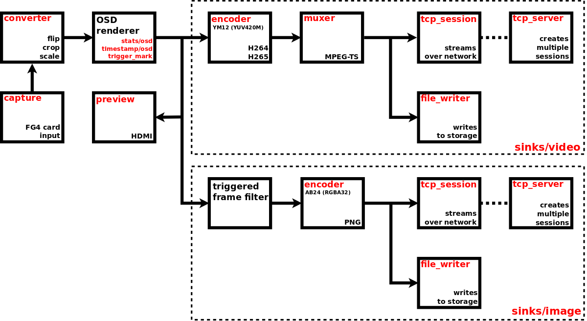
}Next picture shows the component diagram of complete video capture pipeline, with arrows indicating the flow of video frames. Red labels are the names of corresponding objects in configuration and status JSONs, their simplified snippets are shown below the diagram.
Snippet of video capture pipeline configuration (at JSON pointer /video/captures/fg4_001-003-001-018_i0)
{
  "enabled": true,
  "capture": {
    "fg4": {...}
  },
  "nosignal": {
    "enabled": false,
    ...
  },
  "converter": {...},
  "preview": {
    "enabled": false,
    ...
  },
  "sinks": {
    "image": {
      "enabled": false,
      "triggered_mode": false,
      "encoder": {...},
      "file_writer": {...},
      "tcp_server": {...},
      "tcp_session": {...}
    },
    "video": {
      "enabled": true,
      "encoder": {...},
      "muxer": {...},
      "file_writer": {...},
      "tcp_server": {...},
      "tcp_session": {...}
    }
  },
  "stats": {...},
  "timestamp": {...},
  "trigger_mark": {...}
}
Snippet of video capture pipeline status (at JSON pointer /video/captures/fg4_001-003-001-018_i0)
{
  "running": true,
  "capture": {
    "fg4": {
      "running": true,
      ...
    }
  },
  "nosignal": {
    "running": false
  },
  "preview": {
    "running": false
  },
  "sinks": {
    "image": {
      "running": false,
      "file_writer": {...}
    },
    "video": {
      "running": true,
      "file_writer": {...}
    }
  },
  "stats": {...}
}
To enable the video capture pipeline, just set enabled to true. See running property in status to get the real state of video capture pipeline. If the running property is true, then at least capture device or no-signal generator is running. Most individual pipeline components have their own enable (configuration) and running (status) properties. To have the running video capture pipeline, that is fed from capture device, some conditions must be met. Primarily the video capture pipeline must be enabled, the associated physical device must exist and must be ready to provide the video stream (i.e. in case of grabber device, there must be a valid video signal on its input interface).
The following links help to navigate to particular pipeline components (and other stuff).
Currently only one type of physical capture device is supported, namely FG4. So this chapter covers only working with FG4. The configuration and status are located at JSON pointer /video/captures/<name>/capture/fg4.
Snippet of video capture device configuration (at JSON pointer /video/captures/fg4_001-003-001-018_i0/capture/fg4)
{
  "format": {
  },
  "trigger_sources": {
    "signal" : false
  },
  "interface": {
    "fpdl3": {
      "color_mapping": "spwg_vesa",
      "fpdl3_input_width": "automatic",
      "frequency_range": "pll_greater_or_equal_50mhz",
      "hsync_gap_length": 1000,
      "oldi_lane_width": "dual",
      "vsync_gap_length": 2
    },
    "gmsl": {
      "color_mapping": "spwg_vesa",
      "frequency_range": "pll_greater_or_equal_50mhz",
      "gmsl_fec": "enabled",
      "gmsl_mode": "br_12000M",
      "gmsl_stream_id": 1,
      "hsync_gap_length": 1000,
      "oldi_lane_width": "dual",
      "vsync_gap_length": 2
    },
    "gmsl1": {
      "color_mapping": "spwg_vesa",
      "frequency_range": "pll_greater_or_equal_50mhz",
      "hsync_gap_length": 1000,
      "oldi_lane_width": "dual",
      "vsync_gap_length": 2
    }
  }
}
Snippet of video capture device status (at JSON pointer /video/captures/fg4_001-003-001-018_i0/capture/fg4)
{
  "running": true,
  "parent_device": "001-003-001-018",
  "format": {
    "fourcc": "AR24",
    "rate": [150336000, 2391660],
    "size": [1920, 1080]
  },
  "format_descriptions": [
    {
      "fourcc": "AR24",
      "rates": [
        [
          150336000,
          2391660,
          125000000,
          4294967295,
          125000000,
          1
        ]
      ],
      "size": [1920, 1080]
    },
    {
      "fourcc": "YUYV",
      "rates": [
        [
          150336000,
          2391660,
          125000000,
          4294967295,
          125000000,
          1
        ]
      ],
      "size": [1920, 1080]
    }
  ],
  "interface": {
    "fpdl3": {
      "color_mapping": "spwg_vesa",
      "fpdl3_input_width": "automatic",
      "frequency_range": "pll_greater_or_equal_50mhz",
      "hback_porch": 50,
      "hfront_porch": 50,
      "hsync_gap_length": 1000,
      "hsync_status": "active_low",
      "hsync_width": 40,
      "input_id": 0,
      "link_status": "locked",
      "oldi_lane_width": "dual",
      "pclk_frequency": 150338,
      "stream_status": "detected",
      "vback_porch": 31,
      "vfront_porch": 30,
      "video_height": 1080,
      "video_width": 1920,
      "vsync_gap_length": 2,
      "vsync_status": "active_low",
      "vsync_width": 20
    }
  }
}
This type of video capture is a part of FG4 card (actually it represents an input of the interface module), so there exists a reference to this card, property parent_device. It contains the name of parent FG4 card, whose properties can be found at JSON pointer /fg4/devices/<name>. See FG4 PCIe cards chapter to get detailed information.
In general a capture device acts as main source of video frames for the whole video capture pipeline. Only when the element format is present in status, the capture device is ready to provide the video stream (i.e. in case of FG4 card there is a valid video signal on its input interface). The format describes the stream, that is provided by the capture device. When the capture device is running, then format describes the actually flowing stream. When the capture device is not running, then format describes the stream, that will be flowing when the pipeline is enabled (and consequently running) and no custom format is specified. The format has these properties:
fourcc - Pixel format represented as FourCC.
size - Frame size [width, height], in pixels.
rate - Frame rate represented as rational number [num, den], in frames per second.
It is allowed to specify a custom format. If the element format is present in configuration, the capture device tries to provide the stream in specified format. If the specified format cannot be used, then some other is used. Again, when pipeline is running, check format in status to get the actually used format. In configuration the element format is optional and also its all three sub-elements fourcc, size and rate are optional. Currently only fourcc and rate are evaluated, size is ignored. Possible format values can be determined from status element format_descriptions. It is actually an array of allowed formats, where each element has these properties:
fourcc - Pixel format represented as FourCC.
size - Frame size, in pixels. It is represented as [width, height] in case of discrete size, or as [min_width, min_height, max_width, max_height, step_width, step_heigth] in case of step-wise size.
rates - Array of frame rates, in frames per second. Each one is represented as [num, den] in case of discrete rate, or as [max_num, max_den, min_num, min_den, step_num, step_den] in case of step-wise rate. In calculations step must be used as period (not frame rate), with flipped numerator and denominator, e.g. custom_rate = 1/(min_den/min_num + 10 * step_den/step_num).
Element fourcc may contain only AR24 or YUYV. Pixel format AR24 is ABGR with four bytes per pixel, pixel format YUYV is YUV 4:2:2 with four bytes per two pixels. So the YUYV takes only half the bandwidth compared to AR24. On the other hand it may loose some information, because e.g. FPD-Link/GMSL interfaces use the RGB with three bytes per pixel. Omit the fourcc to use the default AR24.
Element rate may be used to set a custom fixed frame rate, which must always be less than the one being captured on hardware interface. It may be useful to reduce the bandwith. Omit the rate to use the value captured on interface.
Element size is ignored as it is always used the value captured on interface.
Although custom pixel format may be specified, after capturing into the pipeline the pixel format is always transformed to the format required by the following pipeline components, e.g. video stream (H264, H265) usually uses YM12 (YUV 4:2:0 planar), image stream (PNG) uses AB24 (RGBA with four bytes per pixel).
Each FG4 capture device can act as trigger source within the Trigger system. The individual sources can be configured in trigger_sources element. Currently there is only one boolean configuration property signal, which enables or disables all input signal related trigger sources. These sources are /video/captures/<name>/capture/fg4/signal/change/on and /video/captures/<name>/capture/fg4/signal/change/off, which generate their triggers whenever a change of video signal occurs on input of FG4 capture device. Value on means, that immediately after the change a valid video signal was detected. Value off means, that immediately after the change no valid video signal was detected.
Each FG4 card may contain an interchangable part named as interface module (or just interface). Each interface may contain one or more video inputs. Each video input is represented by this capture device. Check the status interface element to get the actually used interface type (it contains exactly one sub-element, fpdl3, gmsl or gmsl1). Each interface contains a number of properties, whose actual values are available in status. Some of them can be set to custom value, just put the property into configuration. To use the default (or last set) value, just omit the property from configuration. Currently FPD-Link 3, GMSL 2/3 and GMSL 1 interfaces are supported.
The interface is described by fpdl3 interface sub-element.
List of all existing properties (available in status):
input_id - integer. Input number ID, zero based.
oldi_lane_width - string enum (single, dual). Number of deserializer output lanes.
color_mapping - string enum (oldi_jeida, spwg_vesa). Mapping of the incoming bits in the signal to the colour bits of the pixels.
link_status - string enum (unlocked, locked). Video link status. If the link is locked, chips are properly connected and communicating at the same speed and protocol. The link can be locked without an active video stream.
stream_status - string enum (not_detected, detected). Video stream status. A stream is detected if the link is locked, the input pixel clock is running and the DE signal is moving.
video_width - integer. Video stream width. This is the actual width as detected by the HW.
video_height - integer. Video stream height. This is the actual height as detected by the HW.
vsync_status - string enum (active_low, active_high, not_available). The type of VSYNC pulses as detected by the video format detector.
hsync_status - string enum (active_low, active_high, not_available). The type of HSYNC pulses as detected by the video format detector.
vsync_gap_length - integer. If the incoming video signal does not contain synchronization VSYNC and HSYNC pulses, these must be generated internally in the FPGA to achieve the correct frame ordering. This value indicates, how many empty pixels (pixels with deasserted Data Enable signal) are necessary to generate the internal VSYNC pulse.
hsync_gap_length - integer. If the incoming video signal does not contain synchronization VSYNC and HSYNC pulses, these must be generated internally in the FPGA to achieve the correct frame ordering. This value indicates, how many empty pixels (pixels with deasserted Data Enable signal) are necessary to generate the internal HSYNC pulse. The value must be greater than 1 and smaller than vsync_gap_length.
pclk_frequency - integer. Input pixel clock frequency in kHz.
hsync_width - integer. Width of the HSYNC signal in PCLK pulses.
vsync_width - integer. Width of the VSYNC signal in video lines.
hback_porch - integer. Number of PCLK pulses between deassertion of the HSYNC signal and the first valid pixel in the video line (marked by DE=1).
hfront_porch - integer. Number of PCLK pulses between the end of the last valid pixel in the video line (marked by DE=1) and assertion of the HSYNC signal.
vback_porch - integer. Number of video lines between deassertion of the VSYNC signal and the video line with the first valid pixel (marked by DE=1).
vfront_porch - integer. Number of video lines between the end of the last valid pixel line (marked by DE=1) and assertion of the VSYNC signal.
frequency_range - string enum (pll_less_than_50mhz, pll_greater_or_equal_50mhz). PLL frequency range of the OLDI input clock generator. The PLL frequency is derived from the Pixel Clock Frequency (PCLK) and is equal to PCLK if oldi_lane_width is set to single and PCLK/2 if oldi_lane_width is set to dual.
fpdl3_input_width - string enum (automatic, single, dual). Number of deserializer input lines.
List of configurable properties (may occur in configuration):
oldi_lane_width
color_mapping
vsync_gap_length
hsync_gap_length
frequency_range
fpdl3_input_width
The frame rate may be computed by the formula:
frame_rate = pclk_frequency * 1000/(total_width * total_height)
total_width = video_width + hfront_porch + hback_porch + hsync_width
total_height = video_height + vfront_porch + vback_porch + vsync_width
The interface is described by gmsl interface sub-element.
List of all existing properties (available in status):
input_id - integer. Input number ID, zero based.
oldi_lane_width - string enum (single, dual). Number of deserializer output lanes.
color_mapping - string enum (oldi_jeida, spwg_vesa). Mapping of the incoming bits in the signal to the colour bits of the pixels.
link_status - string enum (unlocked, locked). Video link status. If the link is locked, chips are properly connected and communicating at the same speed and protocol. The link can be locked without an active video stream.
stream_status - string enum (not_detected, detected). Video stream status. A stream is detected if the link is locked, the input pixel clock is running and the DE signal is moving.
video_width - integer. Video stream width. This is the actual width as detected by the HW.
video_height - integer. Video stream height. This is the actual height as detected by the HW.
vsync_status - string enum (active_low, active_high, not_available). The type of VSYNC pulses as detected by the video format detector.
hsync_status - string enum (active_low, active_high, not_available). The type of HSYNC pulses as detected by the video format detector.
vsync_gap_length - integer. If the incoming video signal does not contain synchronization VSYNC and HSYNC pulses, these must be generated internally in the FPGA to achieve the correct frame ordering. This value indicates, how many empty pixels (pixels with deasserted Data Enable signal) are necessary to generate the internal VSYNC pulse.
hsync_gap_length - integer. If the incoming video signal does not contain synchronization VSYNC and HSYNC pulses, these must be generated internally in the FPGA to achieve the correct frame ordering. This value indicates, how many empty pixels (pixels with deasserted Data Enable signal) are necessary to generate the internal HSYNC pulse. The value must be greater than 1 and smaller than vsync_gap_length.
pclk_frequency - integer. Input pixel clock frequency in kHz.
hsync_width - integer. Width of the HSYNC signal in PCLK pulses.
vsync_width - integer. Width of the VSYNC signal in video lines.
hback_porch - integer. Number of PCLK pulses between deassertion of the HSYNC signal and the first valid pixel in the video line (marked by DE=1).
hfront_porch - integer. Number of PCLK pulses between the end of the last valid pixel in the video line (marked by DE=1) and assertion of the HSYNC signal.
vback_porch - integer. Number of video lines between deassertion of the VSYNC signal and the video line with the first valid pixel (marked by DE=1).
vfront_porch - integer. Number of video lines between the end of the last valid pixel line (marked by DE=1) and assertion of the VSYNC signal.
frequency_range - string enum (pll_less_than_50mhz, pll_greater_or_equal_50mhz). PLL frequency range of the OLDI input clock generator. The PLL frequency is derived from the Pixel Clock Frequency (PCLK) and is equal to PCLK if oldi_lane_width is set to single and PCLK/2 if oldi_lane_width is set to dual.
gmsl_mode - string enum (br_12000M, br_6000M, br_3000M, br_1500M). GMSL speed mode.
gmsl_stream_id - integer. The GMSL multi-stream contains up to four video streams. This parameter selects which stream is captured by the video input. The value is the zero-based index of the stream.
gmsl_fec - string enum (disabled, enabled). GMSL Forward Error Correction (FEC).
List of configurable properties (may occur in configuration):
oldi_lane_width
color_mapping
vsync_gap_length
hsync_gap_length
frequency_range
gmsl_mode
gmsl_stream_id
gmsl_fec
The frame rate may be computed by the formula:
frame_rate = pclk_frequency * 1000/(total_width * total_height)
total_width = video_width + hfront_porch + hback_porch + hsync_width
total_height = video_height + vfront_porch + vback_porch + vsync_width
The interface is described by gmsl1 interface sub-element.
List of all existing properties (available in status):
input_id - integer. Input number ID, zero based.
oldi_lane_width - string enum (single, dual). Number of deserializer output lanes.
color_mapping - string enum (oldi_jeida, spwg_vesa, zdml). Mapping of the incoming bits in the signal to the colour bits of the pixels.
link_status - string enum (unlocked, locked). Video link status. If the link is locked, chips are properly connected and communicating at the same speed and protocol. The link can be locked without an active video stream.
stream_status - string enum (not_detected, detected). Video stream status. A stream is detected if the link is locked, the input pixel clock is running and the DE signal is moving.
video_width - integer. Video stream width. This is the actual width as detected by the HW.
video_height - integer. Video stream height. This is the actual height as detected by the HW.
vsync_status - string enum (active_low, active_high, not_available). The type of VSYNC pulses as detected by the video format detector.
hsync_status - string enum (active_low, active_high, not_available). The type of HSYNC pulses as detected by the video format detector.
vsync_gap_length - integer. If the incoming video signal does not contain synchronization VSYNC and HSYNC pulses, these must be generated internally in the FPGA to achieve the correct frame ordering. This value indicates, how many empty pixels (pixels with deasserted Data Enable signal) are necessary to generate the internal VSYNC pulse.
hsync_gap_length - integer. If the incoming video signal does not contain synchronization VSYNC and HSYNC pulses, these must be generated internally in the FPGA to achieve the correct frame ordering. This value indicates, how many empty pixels (pixels with deasserted Data Enable signal) are necessary to generate the internal HSYNC pulse. The value must be greater than 1 and smaller than vsync_gap_length.
pclk_frequency - integer. Input pixel clock frequency in kHz.
hsync_width - integer. Width of the HSYNC signal in PCLK pulses.
vsync_width - integer. Width of the VSYNC signal in video lines.
hback_porch - integer. Number of PCLK pulses between deassertion of the HSYNC signal and the first valid pixel in the video line (marked by DE=1).
hfront_porch - integer. Number of PCLK pulses between the end of the last valid pixel in the video line (marked by DE=1) and assertion of the HSYNC signal.
vback_porch - integer. Number of video lines between deassertion of the VSYNC signal and the video line with the first valid pixel (marked by DE=1).
vfront_porch - integer. Number of video lines between the end of the last valid pixel line (marked by DE=1) and assertion of the VSYNC signal.
frequency_range - string enum (pll_less_than_50mhz, pll_greater_or_equal_50mhz). PLL frequency range of the OLDI input clock generator. The PLL frequency is derived from the Pixel Clock Frequency (PCLK) and is equal to PCLK if oldi_lane_width is set to single and PCLK/2 if oldi_lane_width is set to dual.
List of configurable properties (may occur in configuration):
oldi_lane_width
color_mapping
vsync_gap_length
hsync_gap_length
frequency_range
The frame rate may be computed by the formula:
frame_rate = pclk_frequency * 1000/(total_width * total_height)
total_width = video_width + hfront_porch + hback_porch + hsync_width
total_height = video_height + vfront_porch + vback_porch + vsync_width
No-signal generator is a component allowing to generate auxiliary video signal. The configuration and status are located at JSON pointer /video/captures/<name>/nosignal.
Snippet of no-signal generator configuration (at JSON pointer /video/captures/fg4_001-003-001-018_i0/nosignal)
{
    "enabled" : false,
    "pattern" : "solid_magenta_100",
    "format" : {
        "size" : [640, 480],
        "rate" : [60, 1]
    },
    "follow_capture_format": false
}
Snippet of no-signal generator status (at JSON pointer /video/captures/fg4_001-003-001-018_i0/nosignal)
{
    "running" : false
}
When no signal is present on input of capture device, this generator can be used as alternate source of video signal. When both the signals from capture device and generator are of the same resolution, then the video sources can be swapped without recreating the pipeline, so the running stream will not be broken. Of course, there will always be a small gap between last frame from signal generator and first frame from capture device (and vice versa), typically 8 frames (required by FG4 PCIe card) + additional 50-100 ms (required by Jetson).
enabled - set to true to enable no-signal generator. See running status property to get the real state.
pattern - video signal pattern. It must contain one of these values:
- solid_black
- solid_white_100
- solid_red_100
- solid_green_100
- solid_blue_100
- solid_yellow_100
- solid_cyan_100
- solid_magenta_100
- text_nosignal_white_100
- text_nosignal_white_100_on_blue_100
The generated patterns (frames) are natively represented in RGB, each color component in range from 0x00 (0) to 0xFF (255). The postfix 100 implies the color components of value 0xFF (100).
format/rate - Frame rate represented as rational number [num, den], in frames per second.
format/size - Frame size [width, height], in pixels.
follow_capture_format - When true, then format of generated signal is the same as format of signal from previously running capture device. It means, that switching to generator video source doesn't break the stream. When false, then format of generated signal is determined solely by format configuration property. Also whenever the pipeline gets enabled and no signal is present on input of capture device, format of generated signal is determined by format property.
When the generator is running, its status contains the format element. It has the same structure as format in configuration and describes the real format of generated video stream. In case the follow_capture_format is true, the real format may differ from the one contained in configuration.
Converter is a component allowing to perform some hardware accelerated transformations (resizing, cropping, rotating, flipping etc.). The configuration is located at JSON pointer /video/captures/<name>/converter. There is no status available.
Snippet of converter configuration (at JSON pointer /video/captures/fg4_001-003-001-018_i0/converter)
{
  "size": [0, 0],
  "crop_src": [0, 0, 0, 0],
  "crop_dst": [0, 0, 0, 0],
  "flip": "none",
  "filter": "none"
}
size - Destination frame size [width, height] (in pixels). Must be between [64, 64] and [4096, 4096]. Set to [0, 0] to disable resizing. Any invalid values result in disabled resizing.
crop_src - Source frame cropping parameters [x, y, width, height] (in pixels). Must be between [64, 64] and [4096, 4096]. Set to [0, 0, 0, 0] to disable cropping. Any invalid values result in disabled cropping. When the cropping window exceeds the source frame size, cropping is also disabled.
crop_dst - Destination frame cropping parameters [x, y, width, height] (in pixels). Must be between [64, 64] and [4096, 4096]. Set to [0, 0, 0, 0] to disable cropping. Any invalid values result in disabled cropping. When the cropping window exceeds the destination frame size, cropping is also disabled.
flip - Flipping method (none, rotate_90, rotate_180, rotate_270, flip_x, flip_y, transpose, inverse_transpose).
filter - Filtering (smoothing) method (none, nearest, bilinear, tap_5, tap_10, smart, nicest).
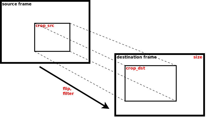
Preview is a component allowing to view the video stream on HDMI. The configuration and status are located at JSON pointer /video/captures/<name>/preview.
Snippet of preview configuration (at JSON pointer /video/captures/fg4_001-003-001-018_i0/preview)
{
  "enabled": false,
  "window": {
    "position": [0, 0],
    "size": [0, 0],
    "border": {
      "width": 0
    },
  }
}
Snippet of preview status (at JSON pointer /video/captures/fg4_001-003-001-018_i0/preview)
{
  "running": false
}
To enable the preview, just set enabled property to true. See running property in status to get the real state of the preview. If the running property is true, then the video frames are rendered to window, whose properties are:
position - Coordinates [x, y] (in pixels) of the top-left corner of rendered window. They are ignored in fullscreen.
size - Size [width, height] (in pixels) of rendered window. It must be greater or equal [64, 64]. Size [0, 0] is translated to fullscreen. Size [1, 1] is translated to the size of original frame. Other combinations (whatever dimension less then 64) are reserved, but currently translated to fullscreen.
border/width - Width (in pixels) of window border.
When no external monitor is detected on HDMI, then preview will not be running, although it is enabled.
Video sink is problably the most typical way of processing the captured video stream. In this sink the video stream is being encoded (H264, H265), muxed (MPEG-TS) and then directly saved to storage or streamed over network. The configuration and status are located at JSON pointer /video/captures/<name>/sinks/video.
Snippet of video sink configuration (at JSON pointer /video/captures/fg4_001-003-001-018_i0/sinks/video)
{
  "enabled": true,
  "encoder": {
    "type": "h264",
    "h264": {
      "profile": "high",
      "bitrate": 33000000,
      "bitrate_peak": 0,
      "idr_interval": 34,
      "iframe_interval": 34,
      "format": {
        "fourcc": "YM12",
        "encoding": "rec601",
        "quantization": "limited"
      }
    },
    "h265": {
      "profile": "main",
      "bitrate": 33000000,
      "bitrate_peak": 0,
      "idr_interval": 34,
      "iframe_interval": 34,
      "format": {
        "fourcc": "YM12",
        "encoding": "rec601",
        "quantization": "limited"
      }
    }
  },
  "muxer": {
    "type": "mpegts",
    "mpegts": {
      "timestamp": {
        "type": "monotonic"
      },
      "allocated_capture_buffers": 64
    }
  },
  "file_writer": {
    "enabled": false,
    "path": "mounts:/satadisk/video/captures/fg4_001-003-001-018_i0/sinks/video/",
    "key_frame_force": false,
    "key_frame_wait": false,
    "enqueued_output_buffers": 64
  },
  "tcp_server": {
    "port": 50180
  },
  "tcp_session": {
    "key_frame_force": false,
    "key_frame_wait": false,
    "enqueued_output_buffers": 32
  }
}
Snippet of video sink status (at JSON pointer /video/captures/fg4_001-003-001-018_i0/sinks/video)
{
  "running": true,
  "file_writer": {
    "running": false
  }
}
To enable the sink, just set enabled property to true. See running property in status to get the real state of the sink. If the running property is true, then at least encoder and muxer are running, also TCP server should be running. When encoder or muxer are not able to run (for whatever reason), then also the sink is not able to run and the running property is false. When TCP server is not able to run (for whatever reason), then it has no impact on the sink and its running property remains unchanged. File writer has its own enabled and running properties.
After the file writer gets running or the TCP client gets connected, they immediately receive frames from already running stream (consisting of encoded and muxed frames). There exists no special file container (mp4, mpv, ...). There exists no additional filtering, e.g. skipping first no-key frames. This is the pretty suitable solution for having low-latency and high-efficiency video stream for multiple recipients. Any DVB-T/S stream works in the same way.
The configuration is located at JSON pointer /video/captures/<name>/sinks/video/encoder. Status is not available. There are multiple types of encoder, so set the type property to select the required one. The type may contain one of these values: h264, h265. The configuration of each particular encoder is then contained in its own property of the same name.
Encoder H264 (also known as AVC or MPEG-4 Part 10) has these configuration properties:
profile - Profile. It may contain one of these values: baseline, main and high.
bitrate - Bitrate (in bits per second), in range from 8192 (1 kiB/s) to 134217728 (16 MiB/s). It is only a hint, so the real bitrate may vary. Typically, if the configured bitrate is too high to be fully utilized to encode the low complexity frames, then the real bitrate will always be less than the configured one.
bitrate_peak - Peak bitrate (in bits per second), in range from 0 to 134217728 (16 MiB/s). If greater than bitrate, then required real bitrate is considered as variable, otherwise it is considered as constant. It is only a hint, so the real bitrate may occur outside the specified range.
idr_interval - Interval between two IDR-frames (in number of frames), in range from 1 to 1024.
iframe_interval - Interval between two I-frames (in number of frames), in range from 1 to 1024.
format/fourcc - Pixel format represented as FourCC. It may contain only YM12 (YUV 4:2:0 planar).
format/encoding - Color encoding (color matrix). It may contain rec601 (Rec.601/BT.601) or rec709 (Rec.709/BT.709).
format/quantization - Color quantization (range). It may contain limited or full.
The encoder is hardware accelerated.
Encoder H265 (also known as HEVC or MPEG-H Part 2) has these configuration properties:
profile - Profile. It may contain one of these values: main.
bitrate - Bitrate (in bits per second), in range from 8192 (1 kiB/s) to 134217728 (16 MiB/s). It is only a hint, so the real bitrate may vary. Typically, if the configured bitrate is too high to be fully utilized to encode the low complexity frames, then the real bitrate will always be less than the configured one.
bitrate_peak - Peak bitrate (in bits per second), in range from 0 to 134217728 (16 MiB/s). If greater than bitrate, then required real bitrate is considered as variable, otherwise it is considered as constant. It is only a hint, so the real bitrate may occur outside the specified range.
idr_interval - Interval between two IDR-frames (in number of frames), in range from 1 to 1024.
iframe_interval - Interval between two I-frames (in number of frames), in range from 1 to 1024.
format/fourcc - Pixel format represented as FourCC. It may contain YM12 (YUV 4:2:0 planar) or YM24 (YUV 4:4:4 planar).
format/encoding - Color encoding (color matrix). It may contain rec601 (Rec.601/BT.601) or rec709 (Rec.709/BT.709). When pixel format is YM24, this property is ignored and rec601 encoding is always used.
format/quantization - Color quantization (range). It may contain limited or full. When pixel format is YM24, this property is ignored and limited quantization is always used.
The encoder is hardware accelerated.
When not sure with format properties, always use YM12, rec601 and limited. They are pretty standard values and moreover it is well known, that not all software is able to use the rec709 encoding and limited quantization properly.
The configuration is located at JSON pointer /video/captures/<name>/sinks/video/muxer. Status is not available. There are multiple types of multiplexer, so set the type property to select the required one. The type may contain one of these values: mpegts. The configuration of each particular multiplexer is then contained in its own property of the same name. Currently only one multiplexer (MPEG-TS) is supported.
Multiplexer MPEG-TS has these configuration properties:
timestamp/type - Type of timestamp used as PTS (presentation timestamp). Possible values are monotonic and stream. See Monotonic time for detailed information. Type stream starts its counting whenever video pipeline gets running. Keep in mind, that PTS treates timestamp as 33-bit number with resolution of 1/90kHz, so it overflows each about 26.5 hour. Therefore System time cannot be used.
allocated_capture_buffers - Number of allocated capture buffers, in range from 1 to 128. They are buffers filled with muxed video and going out from the multiplexer. See Queuing buffers for detailed information.
The configuration and status are located at JSON pointer /video/captures/<name>/sinks/video/file_writer. File writer is responsible for storing the encoded/muxed stream to mounted device (e.g. SATA or USB disk). Destination file is determined by path, which is a string complying with definition of URI (Uniform Resource Identifier), see RFC3986. Only scheme and path components are used within the URI.
Scheme component must always be set to mounts value. It means that one of the mounted devices will be used for writing the file.
Path component represents the file path. It must always start with forward slash character "/". The first segment of the path must always be the name of specific mount point, in general it can be any of mount points located in status at JSON pointer /storage/mounts. See Mounts chapter for detailed description. The following segments represent the rest of the file path within the mount point. The path may contain some special variables, which are replaced by their real values at the time the file is created. These variables must be specified in form $(variable_name). Currently supported variables:
time - system time complying with full date and time according to ISO 8601, with milliseconds
ext - default file extension (including the dot ".") corresponding with used data format
When the path ends with forward slash character "/", it is considered as directory and the file name is constructed automatically as $(time)$(ext). When the path contains non-existent directories, they will be created automatically.
Here are examples of possible paths:
mounts:/satadisk/video/captures/fg4_001-003-001-018_i0/sinks/video/The file is created on storage device, that is mounted to mount point satadisk. Directories video, captures, fg4_001-003-001-018_i0, sinks and video are created automatically if they don't exist. Because the path ends with "/", it is considered as directory and the file name is constructed automatically. So the resulting file name on the mounted device may look something like /video/captures/fg4_001-003-001-018_i0/sinks/video/20240215T105231.517Z.ts.
mounts:/satadisk/captures/fg4_018_$(time)$(ext)The file is created on storage device, that is mounted to mount point satadisk. Directory captures is created automatically if it doesn't exist. The resulting file name on the mounted device may look something like /captures/fg4_018_20240215T105231.517Z.ts.
To enable the file writer, just set enabled to true. See running property in status to get the real state of file writer. To have the running file writer, some conditions must be met. E.g. the whole capture pipeline must be enabled, video sink must be enabled, file writer must be enabled, mount point must exist, mounted device must be writable and must contain enough free space, file name must be correctly specified, valid signal must be present on input of video capture device. When any of these conditions are not met or any errors occur, the file writer stops working and the running state is set to false. Whenever the file writer changes its running state to true, it creates new file and opens it for writing. When the file writer changes its running state to false, it also closes the file.
Video encoder may produce a sequence of frames, that are dependent on specific previous frame, often called as key-frame. Decoder must then wait for the first key-frame to be able to start the full decoding process. Whenever the file writer gets running, its first consumed frame will probably not be the key-frame. To mitigate this situation, two configuration properties are present, key_frame_force and key_frame_wait. Set the key_frame_force to true to force the encoder to produce a key-frame whenever the file writer gets running. Set the key_frame_wait to true to let the file writer wait, so that its first consumed frame is the key-frame. Both the forcing and waiting features are not guaranteed, but the effort is always taken.
The last property is enqueued_output_buffers. It is the maximum number of enqueued output buffers, with minimum of 1. They are buffers coming directly from multiplexer. See Queuing buffers for detailed information.
Encoded/muxed stream may also be transmitted over network as TCP stream. Element tcp_server represents the TCP server, that listens on specified port. Each time it accepts incoming connection, new TCP session is created. Up to 8 TCP sessions may exist at the same time. Each created TCP session is configured with parameters found in tcp_session element. The following text concerns only TCP sessions.
Video encoder may produce a sequence of frames, that are dependent on specific previous frame, often called as key-frame. Decoder must then wait for the first key-frame to be able to start the full decoding process. Whenever the TCP session is created, its first consumed frame will probably not be the key-frame. To mitigate this situation, two configuration properties are present, key_frame_force and key_frame_wait. Set the key_frame_force to true to force the encoder to produce a key-frame whenever the TCP session is created. Set the key_frame_wait to true to let the TCP session wait, so that its first consumed frame is the key-frame. Both the forcing and waiting features are not guaranteed, but the effort is always taken.
The last property is enqueued_output_buffers. It is the maximum number of enqueued output buffers, with minimum of 1. They are buffers coming directly from multiplexer. See Queuing buffers for detailed information.
Image sink is a little special way of processing the captured video stream. In this sink the video stream is being encoded (PNG) into sequence of separated images, and then directly saved to storage (as separated files) or streamed over network (as sequence of images). The configuration and status are located at JSON pointer /video/captures/<name>/sinks/image.
Snippet of image sink configuration (at JSON pointer /video/captures/fg4_001-003-001-018_i0/sinks/image)
{
  "enabled": true,
  "triggered_mode": false,
  "encoder": {
    "type": "png",
    "png": {
      "filter": "none",
      "compression": 6,
      "threads": 2,
      "allocated_capture_buffers": 64,
      "timestamp": {
        "type": "monotonic"
      }
    }
  },
  "file_writer": {
    "enabled": false,
    "path": "mounts:/satadisk/video/captures/fg4_001-003-001-018_i0/sinks/image/",
    "enqueued_output_buffers": 64,
    "ring_buffer": {
      "enabled": true,
      "size": 100
    }
  },
  "tcp_server": {
    "port": 50184
  },
  "tcp_session": {
    "enqueued_output_buffers": 32
  }
}
Snippet of image sink status (at JSON pointer /video/captures/fg4_001-003-001-018_i0/sinks/image)
{
  "running": true,
  "file_writer": {
    "running": false
  }
}
To enable the sink, just set enabled property to true. See running property in status to get the real state of the sink. If the running property is true, then at least encoder is running, also TCP server should be running. When encoder is not able to run (for whatever reason), then also the sink is not able to run and the running property is false. When TCP server is not able to run (for whatever reason), then it has no impact on the sink and its running property remains unchanged. File writer has its own enabled and running properties.
After the file writer gets running or the TCP client gets connected, they immediately receive frames from already running stream (consisting of encoded frames - images).
Due to its nature the image sink may operate in so called "triggered" mode. To enable this mode, just set triggered_mode property to true. In this mode the normal streaming of images is blocked and the image is passed only when a dedicated nonparametric synchronous action at URL path
/api/app/actions/video/captures/<name>/sinks/image/trigger_imageis called. Every call of this action is buffered. Then, when a frame is captured (by captured device) and the buffer of actions is not empty, the frame is passed and the buffer of actions is cleaned. The buffer is also cleaned whenever the image sink changes its state to running. Of course, the action can be used as Trigger sink within the Trigger system. In this case all participating triggers are stored (if possible) as metadata in the passed image. Actually, when the action is called directly by HTTP API (not as trigger sink), the action is also stored, the same way as the trigger, but with empty trigger identifier. See the particular encoder chapters how the triggers are stored in the image.
Although the captured video frames and generated triggers have their own timestamps, there exists no their explicit timestamp-based synchronization when working in triggered mode. Typically, the triggers are generated (and timestamped) in their own threads, the video frames are captured (and timestamped) in their own threads and also the trigger-based video frame filter works in its own thread. The filter processes the triggers and frames as they are comming, as fast as possible and without any specific timestamp-based synchronization. So the time-based closeness depends primarily on CPU power. This behaviour results from the fact, that the precision of assigning the timestamps to the triggers and video frames also depends primarily on CPU power and within the current Linux system it can't be solved in a better way. So the timestamps difference between the passed video frame and its trigger is absolutely as small as possible (dependent on CPU power), but it may have both positive and negative sign. See the Examples how the timestamps may look like.
The configuration is located at JSON pointer /video/captures/<name>/sinks/image/encoder. Status is not available. There are multiple types of encoder, so set the type property to select the required one. The type may contain one of these values: png. The configuration of each particular encoder is then contained in its own property of the same name. Currently only one encoder (PNG) is supported.
Encoder PNG has these configuration properties:
filter - Filter type, may contain one of these values: none, sub, up, avg, paeth. The purpose of the filter is to prepare the image data for optimum compression.
compression - Compression level, in range from 0 to 9. Zero level means no compression.
threads - Number of threads performing the compression, in range from 1 to 6.
allocated_capture_buffers - Number of allocated capture buffers, in range from 1 to 128. They are buffers filled with encoded images and going out from encoder. See Queuing buffers for detailed information.
timestamp/type - Type of all timestamps stored in key-value tEXt chunks. Possible values are monotonic and system. See Monotonic time and System time for detailed information.
The encoder is lossless and always uses RGBA pixel format, with four bytes per pixel. The frames are converted automatically. The encoder is not hardware accelerated, but it provides the possibility to set the number of threads performing the compression. Increasing the threads property increases the frame rate, of course, the latency remains unchanged. Note that increasing the threads property causes more consumed CPU power, so it may have significant impact on the rest of the system. Interesting possibility to increase the frame rate, decrease latency and save CPU power is to decrease the compression property, of course at the cost of increased bandwidth. Also the filter property has significant impact on CPU power, e.g. setting to none totally disables the filtering, so it saves CPU power, of course, at the cost of worse compression. Setting filter to none and compression to 0 results in streaming totally unencoded (raw) image data, so it usually saves maximum CPU power but consumes maximum bandwidth.
PNG format allows to store additional textual metadata. This is used for storing the timestamp and trigger, both in key-value tEXt chunks.
Frame timestamp is identified by the key ts, the value contains the timestamp, as integer number in nanoseconds. Type of the timestamp is determined by property timestamp/type.
Trigger is identified by the key tr, the value contains the trigger, as JSON object. See the Trigger for detailed information. Multiple triggers are stored as multiple key-value chunks. All stored triggers contain timestamp, whose type is determined by property timestamp/type.
The configuration and status are located at JSON pointer /video/captures/<name>/sinks/image/file_writer. File writer is responsible for storing the encoded frames to mounted device (e.g. SATA or USB disk). Each frame is stored to its own separate file. The file is determined by path, which is a string complying with definition of URI (Uniform Resource Identifier), see RFC3986. Only scheme and path components are used within the URI.
Scheme component must always be set to mounts value. It means that one of the mounted devices will be used for writing the file.
Path component represents the file path. It must always start with forward slash character "/". The first segment of the path must always be the name of specific mount point, in general it can be any of mount points located in status at JSON pointer /storage/mounts. See Mounts chapter for detailed description. The following segments represent the rest of the file path within the mount point. The path may contain some special variables, which are replaced by their real values at the time the file is created. These variables must be specified in form $(variable_name). Currently supported variables:
time - system time complying with full date and time according to ISO 8601, with milliseconds
ext - default file extension (including the dot ".") corresponding with used data format
When the path ends with forward slash character "/", it is considered as directory and the file name is constructed automatically as $(time)$(ext). When the path contains non-existent directories, they will be created automatically.
Here are examples of possible paths:
mounts:/satadisk/video/captures/fg4_001-003-001-018_i0/sinks/image/The file is created on storage device, that is mounted to mount point satadisk. Directories video, captures, fg4_001-003-001-018_i0, sinks and image are created automatically if they don't exist. Because the path ends with "/", it is considered as directory and the file name is constructed automatically. So the resulting file name on the mounted device may look something like /video/captures/fg4_001-003-001-018_i0/sinks/image/20240215T105231.517Z.png.
mounts:/satadisk/captures/fg4_018_$(time)$(ext)The file is created on storage device, that is mounted to mount point satadisk. Directory captures is created automatically if it doesn't exist. The resulting file name on the mounted device may look something like /captures/fg4_018_20240215T105231.517Z.png.
To enable the file writer, just set enabled to true. See running property in status to get the real state of file writer. To have the running file writer, some conditions must be met. E.g. the whole capture pipeline must be enabled, image sink must be enabled, file writer must be enabled, mount point must exist, mounted device must be writable and must contain enough free space, file name must be correctly specified, valid signal must be present on input of video capture device. When any of these conditions are not met or any errors occur, the file writer stops working and the running state is set to false.
Because each frame is stored to its own separate file, the number of created files may grow very quickly and the filesystem may get overloaded very easily. Therefore the file writer is equipped with ring buffer, that allows to keep only specified number of latest files. The buffer remembers created files (full paths) and when their number exceeds specified size, the oldest ones are deleted. When ring buffer is disabled, whole remembered history of created files is lost, but created files still remain on storage. The configuration is contained in property ring_buffer. The property enabled enables/disables ring buffer (by default it is always enabled), the property size determines the size of ring buffer, it means the number of latest files being kept on storage.
The last property is enqueued_output_buffers. It is the maximum number of enqueued output buffers, with minimum of 1. They are buffers coming directly from encoder. See Queuing buffers for detailed information.
Encoded frames may also be transmitted over network as TCP stream. Element tcp_server represents the TCP server, that listens on specified port. Each time it accepts incoming connection, new TCP session is created. Up to 8 TCP sessions may exist at the same time. Each created TCP session is configured with parameters found in tcp_session element. It has only one single property enqueued_output_buffers. It is the maximum number of enqueued output buffers, with minimum of 1. They are buffers coming directly from encoder. See Queuing buffers for detailed information.
When the video pipeline is running, some useful statistics are being computed. The configuration and status are located at JSON pointer /video/captures/<name>/stats.
Snippet of statistics configuration (at JSON pointer /video/captures/fg4_001-003-001-018_i0/stats)
{
  "osd": {
    "enabled": true,
    "position": [0, 28],
    "size": 10
  }
}
Snippet of statistics status (at JSON pointer /video/captures/fg4_001-003-001-018_i0/stats)
{
  "data": {
    "capture": {
      "rate": 62.72,
      "rate_data": 520185174,
      "delay": 0.00028,
      "passed": 1040,
      "dropped": 0
    },
    "converter": {...},
    "sinks": {
      "image": {
        "encoder": {...},
        "file_writer": {...},
        "tcp_sessions": {
          "192.168.1.114:43430": {...}
          "192.168.1.114:43432": {...}
          "192.168.1.115:44428": {...}
        }
      },
      "video": {
        "encoder": {...},
        "muxer": {...},
        "file_writer": {...},
        "tcp_sessions": {
          "192.168.1.114:47848": {...}
          "192.168.1.114:47850": {...}
          "192.168.1.115:48846": {
            "delay": 0.02366,
            "dropped": 0,
            "passed": 820,
            "rate": 62.97,
            "rate_data": 282600
          }
        }
      }
    }
  }
}
The statistics are quite rough numbers, rather intended for quick insight or debug purposses. They are present in status or may also be rendered into the running video stream as OSD window. The configuration properties are:
osd/enabled - If true, then OSD window is enabled.
osd/position - Coordinates [x, y] (in pixels) of the top-left corner of rendered OSD window.
osd/size - Font size.
The computed statistics are contained in status element data. Its sub-elements representing the structure of video pipeline components are:
capture - Capture device.
nosignal - No-signal generator.
converter - Converter.
sinks/video/encoder - Video sink encoder.
sinks/video/muxer - Video sink muxer.
sinks/video/file_writer - Video sink file writer.
sinks/video/tcp_sessions/<ip>:<port> - Video sink TCP session.
sinks/image/encoder - Image sink encoder.
sinks/image/file_writer - Image sink file writer.
sinks/image/tcp_sessions/<ip>:<port> - Image sink TCP session.
Each of these elements is present only if the corresponding pipeline component is running. Each element contains these properties:
rate - Number of passed buffers per second. Typically one buffer contains one video frame, so in this case the value equals the frame rate.
rate_data - Number of passed bytes per second.
delay - Delay (in seconds) of the buffer at time of leaving the component. It is measured relatively to the time at which the buffer was received by driver of the underlying linux video device. As shown in the JSON status snippet, it took about 23 milliseconds from capturing the buffer till passing it into the 192.168.1.115:48846 video sink TCP socket.
passed - Number of buffers, that were passed through the component. It is counted from the time at which the component switched to running state.
dropped - Number of buffers, that couldn’t be passed through the component (e.g. it was busy) and thus were dropped. It is counted from the time at which the component switched to running state. It is very typical for PNG image sink encoder to have many dropped buffers, because it is not hardware accelerated. Slow TCP client, network or file storage may also result in growing number of dropped buffers by the corresponding pipeline component. To get the number of buffers dropped along multiple pipeline components, just sum the dropped buffers from all participating components. E.g. to get the total number of dropped buffers on the path between capture device and video sink TCP client, sum dropped buffers from capture, converter, sinks/video/encoder, sinks/video/muxer and particular session from sinks/video/tcp_sessions.
Currently it is true for all pipeline components, that one buffer contains one frame.
If enabled, the statistics are also rendered into the running video stream as OSD window. The example of statistics OSD window:
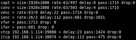
Each line begins with shortened name of the video pipeline component followed by its statistics. Possible components are:
capt - Capture device, the same as capture in status.
nsig - No-signal generator, the same as nosignal in status.
conv - Converter, the same as converter in status.
venc - Video sink encoder, the same as sinks/video/encoder in status.
vmux - Video sink muxer, the same as sinks/video/muxer in status.
ienc - Image sink encoder, the same as sinks/image/encoder in status.
vfwr - Video sink file writer, the same as sinks/video/file_writer in status.
ifwr - Image sink file writer, the same as sinks/image/file_writer in status.
vtcp <ip>:<port> - Video sink TCP session, the same as sinks/video/tcp_sessions/<ip>:<port> in status.
itcp <ip>:<port> - Image sink TCP session, the same as sinks/image/tcp_sessions/<ip>:<port> in status.
The following statistics are:
size - Size (width x height) of the video frame.
rate - The first number has the same meaning as rate in status, but it is truncated to integer. The second number has the same meaning as rate_data in status, but it is expressed as truncated integer in mebibytes (MiB/s).
delay - It has the same meaning as delay in status, but it is expressed as truncated integer in milliseconds.
pass - It is the same value is passed in status.
drop - It is the same value is dropped in status.
Timestamp configuration is located at JSON pointer /video/captures/<name>/timestamp. Status is not available.
Snippet of timestamp configuration (at JSON pointer /video/captures/fg4_001-003-001-018_i0/timestamp)
{
  "osd": {
    "binary": {
      "enabled": false,
      "position": [0, 0],
      "size": [2, 2],
      "type": "monotonic"
    },
    "text": {
      "enabled": false,
      "position": [0, 4],
      "size": 10,
      "type": "monotonic",
      "system_time_format": "human_zoned_msec_zone"
    }
  }
}
Each frame going from Capture device contains the timestamp. In case of FG4 capture device the timestamp is assigned in linux driver, immediately after the frame is received from PCIe bus. Natively the Monotonic time is used as the time base, although it may be converted to System time before presenting (via OSD, network or storage) to user. The type of presented timestamp can usually be selected at all those pipeline components, that somehow put the timestamp into the data stream. Here the OSD rendering is described.
First, the timestamp is rendered in binary form, in nanoseconds, as 64-bit number, with LSB at the right side and MSB at the left side. To enable this feature, just set enabled property to true. The position property (in pixels) determines the position [x, y] of the top-left part of the rendered timestamp. The size property (in pixels) determines the size [width, height] of the single rendered bit. The bits are rendered in RGB with 8-bit per color component, where '0' bits are black (all color components are 0x00) and '1' bits are white (all color components are 0xFF). Type of rendered timestamp can be selected by property type, whose possible value is monotonic or system.
Second, the timestamp is rendered in human readable text form. To enable this feature, just set enabled property to true. The position property (in pixels) determines the position [x, y] of the top-left part of the rendered timestamp. The size property determines the size of the used font. Type of rendered timestamp can be selected by property type, whose possible value is monotonic or system. Monotonic timestamp is always rendered as integer number in nanoseconds. System timestamp is rendered in format determined by property system_time_format, whose possible values are:
unix_sec - Unix time, integer number in seconds.
unix_msec - Unix time, integer number in milliseconds.
unix_usec - Unix time, integer number in microseconds.
unix_nsec - Unix time, integer number in nanoseconds.
iso8601_zoned_sec_offset - Full date and time according to ISO 8601, zoned, with seconds, with UTC offset, e.g. “2023-12-07T13:26:08+01:00”.
iso8601_zoned_msec_offset - Full date and time according to ISO 8601, zoned, with milliseconds, with UTC offset, e.g. “2023-12-07T13:26:08.246+01:00”.
human_zoned_sec_zone - Human readable date and time, zoned, with seconds, with zone, e.g. “2023-12-07 13:26:08 CET”.
human_zoned_msec_zone - Human readable date and time, zoned, with milliseconds, with zone, e.g. “2023-12-07 13:26:08.246 CET”.
Trigger mark configuration is located at JSON pointer /video/captures/<name>/trigger_mark. Status is not available.
Snippet of trigger mark configuration (at JSON pointer /video/captures/fg4_001-003-001-018_i0/trigger_mark)
{
  "position": [0, 0],
  "size": 10
}
Trigger mark is a custom text rendered into the running video stream for a specified time. The configuration properties are:
position - Coordinates [x, y] (in pixels) of the top-left corner of the first (oldest) rendered trigger mark. When multiple trigger marks have to be rendered at the same time, they are serialized by their creation time into one single column, with the oldest one at the top and with the latest one at the bottom.
size - Font size.
To create a trigger mark, just call this parametric synchronous action at URL path
/api/app/actions/video/captures/<name>/trigger_markwith parameter being a JSON object like this:
{
  "text" : "My custom trigger mark",
  "timeout" : 1000
}
text - Text to be rendered as trigger mark.
timeout - Duration (in milliseconds) for which the trigger mark is being rendered.
Although the trigger mark has the word trigger in its name (for historical reasons), actually it has nothing much to do with Trigger system. Except one simple fact, creating trigger mark is done by calling the action, so it can be used as Trigger sink.
This chapter describes a little bit internal topic, but it should help to understand some special parameters occurring by some video pipeline components. The chapter explains how the data are transferred between the video pipeline components.
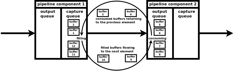
Each pipeline component capable of consuming data has at least one special queue, called output queue, that is designated to receive data from the previous component. Each pipeline component capable of producing data has at least one special queue, called capture queue, that is designated to transmit data to the next component. The naming of the queues may seem confusing, but it is not when you realize, that they are named from the outer point (rest of the pipeline), not from the inner point (the affected pipeline component). This naming convention just mirrors the convention used by video subsystem used by Linux (Video4Linux aka. V4L).
Each pair of neighbouring queues (capture queue of the producing component and output queue of the consuming component) has a fixed number of allocated buffers, that continuously transfer the video data of specific format from the producing component (producer) to the consuming component (consumer). Usually one buffer contains one frame. At the beginning, when the pipeline is initialized, all buffers are enqueued in capture queue of the producer. The producer starts to fill the enqueued buffers (writes data) and once the buffers are filled they are dequeued from the capture queue. Then the filled buffers are enqueued to output queue of the consumer. The consumer starts to consume the enqueued buffers (reads data) and once the buffers are consumed they are dequeued from the output queue. Then the consumed buffers are enqueud to capture buffer of the producer and the process repeats.
There may exist multiple consumers connected to one producer. In this case the filled buffers are enqueued to all connected producers at the same time (the buffers are just pointers). After and only after the buffers are dequeued from all consumers, they are again enqueued back to the producer. Although this kind of zero-copy implementation is very effective, it has a potential drawback. When one of the consumer is not able to consume the enqueued buffers at sufficient speed, then remaining consumers are affected as well. In the worst case the slow consumer may exhaust all allocated buffers (they are kept in its output queue) and so there is no free buffer, that can be used to transfer data between the producer and the remaining consumers. To prevent this situation, some components contain the configurable limit for number of simultaneously enqueued buffers in their output queues. This limit can be set by property enqueued_output_buffers and currently it is present in video sink file writer, video sink TCP session, image sink file writer and image sink TCP session components. The number of all allocated buffers can be set by property allocated_capture_buffers and currently it is present in video sink muxer MPEG-TS and image sink encoder PNG.
When the buffer can't be enqueued to the output queue of the consumer (e.g. due to limit of simultaneously enqueued buffers), it is considered as dropped and when no other consumer exists, it is enqueued back to the producer's capture queue. Number of dropped buffers/frames may be observed in Statistics. On the other hand, when all allocated buffers are enqueued in the output queue of the consumer (e.g. there exists no limit of simultaneously enqueued buffers and the consumer is too slow), then the lack of free buffers is transferred to the previous component. Its capture queue is empty, so it is not able to consume buffers in its output queue and the situation repeats.
Check if video pipeline (at its top level) is running.
curl -v -X GET 'http://192.168.1.200/api/app/status/video/captures/fg4_001-003-001-018_i0/running'Enable video pipeline (at its top level).
curl -v -X PUT -H 'Content-Type: application/json' -d 'true' 'http://192.168.1.200/api/app/config/video/captures/fg4_001-003-001-018_i0/enabled'Enable video pipeline, preview, video sink and video sink file writer with one command.
curl -v -X PATCH -H 'Content-Type: application/json' -d '{"enabled":true,"preview":{"enabled":true},"sinks":{"video":{"enabled":true,"file_writer":{"enabled":true}}}}' 'http://192.168.1.200/api/app/config/video/captures/fg4_001-003-001-018_i0'Get properties of FPD-Link 3 interface of FG4 card.
curl -v -X GET 'http://192.168.1.200/api/app/status/video/captures/fg4_001-003-001-018_i0/capture/fg4/interface/fpdl3'Get format of video signal, that is (or 'will be' if currently not enabled) sourced into the video pipeline by FG4 capture device. Note, that JSON element format exists only when valid video signal is present on input of FG4 capture device. If there is no valid video signal, then the JSON element doesn't exist and the server doesn't respond with 200 (ok).
curl -v -X GET 'http://192.168.1.200/api/app/status/video/captures/fg4_001-003-001-018_i0/capture/fg4/format'Create trigger mark
curl -v -X POST -H 'Content-Type: application/json' -d '{"text":"My custom trigger mark","timeout":1000}' 'http://192.168.1.200/api/app/actions/video/captures/fg4_001-003-001-018_i0/trigger_mark'Trigger image (image sink must be in triggered mode)
curl -v -X POST 'http://192.168.1.200/api/app/actions/video/captures/fg4_001-003-001-018_i0/sinks/image/trigger_image'Print tEXt chunks contained in PNG file
pngcheck -t -q image.pngPossible output of command pngcheck -t -q image.png. Key ts contains image timestamp. Key tr contains trigger, that created the image. It is obvious (because of existing tr key), that the image was created in triggered mode by action /video/captures/<name>/sinks/image/trigger_image. In this case the action was called as trigger sink, whose trigger source was the expiration of timer t0. Timestamps difference is -1.9ms.
File: image.png (72237 bytes)
ts:
    514842528000
tr:
    {"id":"/timer/devices/t0/shot","ts":514844439596}
Possible output of command pngcheck -t -q image.png. Key ts contains image timestamp. Key tr contains trigger, that created the image. It is obvious (because of existing tr key), that the image was created in triggered mode by action /video/captures/<name>/sinks/image/trigger_image. In this case the action was called as trigger sink, whose trigger source was the call of parametric synchronous action at URL path /api/app/actions/trigger/send with parameter tr0. Timestamps difference is -2.8ms.
File: image.png (72909 bytes)
ts:
    423846699000
tr:
    {"id":"/control/tcp_session/tr0","ts":423849467195}
Possible output of command pngcheck -t -q image.png. Key ts contains image timestamp. Key tr contains trigger, that created the image. It is obvious (because of existing tr key), that the image was created in triggered mode by action /video/captures/<name>/sinks/image/trigger_image. In this case (because of empty id) the nonparametric synchronous action at URL path /api/app/actions/video/captures/<name>/sinks/image/trigger_image was called via HTTP API. Timestamps difference is 10.8ms.
File: image.png (75873 bytes)
ts:
    193064627000
tr:
    {"id":"","ts":193053840419}
Possible output of command pngcheck -t -q image.png. Key ts contains image timestamp. It is obvious (because of missing tr key), that the image was created in normal (non-triggered) mode.
File: image.png (261858 bytes)
ts:
65092348053000Next picture shows the component diagram of complete video output pipeline, with arrows indicating the flow of video frames. Red labels are the names of corresponding objects in configuration and status JSONs, their simplified snippets are shown below the diagram.
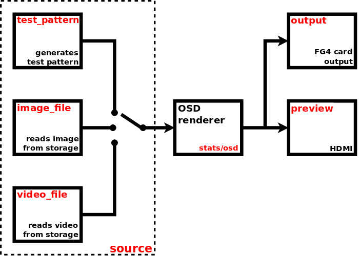
Snippet of video output pipeline configuration (at JSON pointer /video/outputs/fg4_001-003-001-018_o0)
{
  "enabled": true,
  "source": {
    "type": "test_pattern",
    "test_pattern": {...},
    "image_file": {...},
    "video_file": {...}
  },
  "preview": {...},
  "output": {
    "fg4": {...}
  },
  "stats": {...}
}
Snippet of video output pipeline status (at JSON pointer /video/outputs/fg4_001-003-001-018_o0)
{
  "running": true,
  "preview": {...},
  "output": {
    "fg4": {...}
  },
  "stats": {...}
}
To enable the video output pipeline, just set enabled to true. See running property in status to get the real state of video output pipeline. If the running property is true, then at least the source component is running (i.e. video frames are captured from the selected source). Preview and output device have their own separate enable property. To have the running video output pipeline, some conditions must be met. Primarily the video output pipeline must be enabled and the selected video source must be ready to provide the video stream (i.e. in case of image/video file source, there must exist a valid image/video file on storage).
In contrast to the video capture pipeline, in video output pipeline the associated physical device acts as video stream consumer, so it is not required to be ready to consume the video stream in order to have the running pipeline.
The following links help to navigate to particular pipeline components.
The source component acts as essential source of video frames for the whole video output pipeline. The configuration is located at JSON pointer /video/outputs/<name>/source. Status is not available.
Snippet of video source configuration (at JSON pointer /video/outputs/fg4_001-003-001-018_o0/source)
{
  "type": "test_pattern",
  "test_pattern": {
    "pattern": "colorbars_v_100",
    "format": {
      "rate": [60, 1],
      "size": [1920, 1080]
    }
  },
  "image_file": {
    "path": "mounts:/satadisk/image.png",
    "format": {
      "rate": [60, 1]
    }
  },
  "video_file": {
    "path": "mounts:/satadisk/video.ts",
    "hw_accel": false
  }
}
There are multiple types of video source, so set the type property to select the required one. The type may contain one of these values: test_pattern, image_file, video_file. The configuration of each particular type is then contained in its own property of the same name.
Test pattern source generates the stream by repeating the predefined pattern. The configuration is located at JSON pointer /video/outputs/<name>/source/test_pattern. It contains these properties:
pattern - Test pattern. It must contain one of these values:
- solid_black
- solid_white_100
- solid_red_100
- solid_green_100
- solid_blue_100
- solid_yellow_100
- solid_cyan_100
- solid_magenta_100
- colorbars_v_75
- colorbars_v_100
- colorbars_h_75
- colorbars_h_100
- colorsquares_75
- colorsquares_100
- clock_analog_white_100
- clock_analog_red_100
- clock_analog_green_100
- clock_analog_blue_100
The generated patterns (frames) are natively represented in RGB, each color component in range from 0x00 (0) to 0xFF (255). The postfix 100 implies the color components of value 0xFF (100), the postfix 75 implies the color components of value 0xBF (191).
format/rate - Frame rate represented as rational number [num, den], in frames per second.
format/size - Frame size [width, height], in pixels.
Image file source generates the stream by repeating the image loaded from specified file. It is expected, that the file contains one single image, encoded in any supported format (PNG, JPG, ...). The configuration is located at JSON pointer /video/outputs/<name>/source/image_file. It contains these properties:
path - Location of the image file. It is a string complying with definition of URI (Uniform Resource Identifier), see RFC3986. Two URI schemes are supported, mounts and tcp.
When the URI component scheme is mounts, then one of the mounted devices is used for loading the file. In this case URI component path is used. It must always start with forward slash character "/". The first segment of the path must always be the name of specific mount point, in general it can be any of mount points located in status at JSON pointer
/storage/mounts. See Mounts chapter for detailed description. The following segments represent the rest of the file path within the mount point. E.g. when the path ismounts:/satadisk/images/image.png, then the image is loaded from path/images/image.pnglocated on storage mounted to mount pointsatadisk.
When the URI component scheme is tcp, then the TCP socket is used for loading the file. In this case URI components host and port are used. E.g. when the path is
tcp://192.168.1.1:8888, then the image is loaded from TCP server listening on address 192.168.1.1 and port 8888. Note, that more than one connection may be required before the image file source begins to feed the stream into the video pipeline. Typically the first connection loads the image only to determine its parameters (required for creating pipeline) and the second connection loads the image for immediate streaming (within the already created pipeline).
format/rate - Frame rate represented as rational number [num, den], in frames per second.
Video file source provides the stream loaded from specified file. It is expected, that the file contains at least one video stream, encoded/muxed in any supported container (TS, MP4, MKV, AVI, ...). The first found stream is always used. The configuration is located at JSON pointer /video/outputs/<name>/source/video_file. It contains these properties:
path - Location of the video file. It is a string complying with definition of URI (Uniform Resource Identifier), see RFC3986. Two URI schemes are supported, mounts and tcp.
When the URI component scheme is mounts, then one of the mounted devices is used for loading the file. In this case URI component path is used. It must always start with forward slash character "/". The first segment of the path must always be the name of specific mount point, in general it can be any of mount points located in status at JSON pointer
/storage/mounts. See Mounts chapter for detailed description. The following segments represent the rest of the file path within the mount point. E.g. when the path ismounts:/satadisk/videos/video.ts, then the stream is loaded from path/videos/video.tslocated on storage mounted to mount pointsatadisk.
When the URI component scheme is tcp, then the TCP socket is used for loading the file. In this case URI components host and port are used. E.g. when the path is
tcp://192.168.1.1:8888, then the stream is loaded from TCP server listening on address 192.168.1.1 and port 8888. Note, that more than one connection may be required before the video file source begins to feed the stream into the video pipeline. Typically the first connection loads a few frames only to determine their parameters (required for creating pipeline) and the second connection begins to continuously load the whole stream for immediate streaming (within the already created pipeline). Also when loading video from TCP, low latency policy is applied. It means only necessary buffering (to keep minimum delay) and allowed frame dropping (to keep sychronization with PTS).
hw_accel - If true, then hardware accelerated decoding will be used if possible. Currently it works only on H264 and H265 codecs with YM12 (YUV 4:2:0 planar) or NV12 pixel formats.
Preview is a component allowing to view the video stream on HDMI. The configuration and status are located at JSON pointer /video/outputs/<name>/preview.
Snippet of preview configuration (at JSON pointer /video/outputs/fg4_001-003-001-018_o0/preview)
{
  "enabled": false,
  "window": {
    "position": [0, 0],
    "size": [0, 0],
    "border": {
      "width": 0
    },
  }
}
Snippet of preview status (at JSON pointer /video/outputs/fg4_001-003-001-018_o0/preview)
{
  "running": false
}
To enable the preview, just set enabled property to true. See running property in status to get the real state of the preview. If the running property is true, then the video frames are rendered to window, whose properties are:
position - Coordinates [x, y] (in pixels) of the top-left corner of rendered window. They are ignored in fullscreen.
size - Size [width, height] (in pixels) of rendered window. It must be greater or equal [64, 64]. Size [0, 0] is translated to fullscreen. Size [1, 1] is translated to the size of original frame. Other combinations (whatever dimension less then 64) are reserved, but currently translated to fullscreen.
border/width - Width (in pixels) of window border.
When no external monitor is detected on HDMI, then preview will not be running, although it is enabled.
Currently only one type of physical output device is supported, namely FG4. So this chapter covers only working with FG4. The configuration and status are located at JSON pointer /video/outputs/<name>/output/fg4.
NOTE:
Current firmware doesn’t support GMSL 2/3 outputs. Although they may be present both in status and configuration, they do not actually work.
Snippet of video output device configuration (at JSON pointer /video/outputs/fg4_001-003-001-018_o0/output/fg4)
{
  "enabled": true,
  "format": {
  },
  "interface": {
    "fpdl3": {
      "color_mapping": "spwg_vesa",
      "display_height": 1080,
      "display_width": 1920,
      "fpdl3_output_width": "dual",
      "frame_rate": 0,
      "pclk_frequency": 150000,
      "video_source": "v4l2_output_0"
    },
    "gmsl": {
      "color_mapping": "spwg_vesa",
      "display_height": 1080,
      "display_width": 1920,
      "frame_rate": 0,
      "pclk_frequency": 150000
    },
    "gmsl1": {
      "color_mapping": "spwg_vesa",
      "display_height": 1080,
      "display_width": 1920,
      "frame_rate": 0,
      "pclk_frequency": 90000,
      "video_source": "v4l2_output_0"
    }
  }
}
Snippet of video output device status (at JSON pointer /video/outputs/fg4_001-003-001-018_o0/output/fg4)
{
  "running": true,
  "format": {
    "fourcc": "AR24",
    "rate": [150000000, 2391660],
    "size": [1920, 1080]
  },
  "format_descriptions": [
    {
      "fourcc": "AR24",
      "rates": [
        [
          150000000,
          2391660,
          125000000,
          4294967295,
          125000000,
          1
        ]
      ],
      "size": [1920, 1080]
    },
    {
      "fourcc": "YUYV",
      "rates": [
        [
          150000000,
          2391660,
          125000000,
          4294967295,
          125000000,
          1
        ]
      ],
      "size": [1920, 1080]
    }
  ],
  "interface": {
    "fpdl3": {
      "color_mapping": "spwg_vesa",
      "de_polarity": "active_high",
      "display_height": 1080,
      "display_width": 1920,
      "fpdl3_output_width": "dual",
      "frame_rate": 200,
      "hback_porch": 50,
      "hfront_porch": 50,
      "hsync_polarity": "active_low",
      "hsync_width": 40,
      "output_id": 0,
      "pclk_frequency": 150000,
      "vback_porch": 31,
      "vfront_porch": 30,
      "video_source": "v4l2_output_0",
      "vsync_polarity": "active_low",
      "vsync_width": 20
    }
  },
  "parent_device": "001-003-001-018"
}
This type of video output is a part of FG4 card (actually it represents an output of the interface module), so there exists a reference to this card, property parent_device. It contains the name of parent FG4 card, whose properties can be found at JSON pointer /fg4/devices/<name>. See FG4 PCIe cards chapter to get detailed information.
To enable the output device, just set the enabled property to true. See running property in status to get the real state of output device. If the running property is true, then the video frames are consumed from the pipeline and should occur at the corresponding output of FG4 card's interface.
In general an output device acts as consumer of video frames from video output pipeline. Only when the element format is present in status, the output device is ready to consume the video stream. The format describes the stream, that must be provided to the output device. When the device is running, then format describes the actually flowing stream. When the device is not running, then format describes the stream, that will be flowing when the device is enabled (and consequently running) and no custom format is specified. The format has these properties:
fourcc - Pixel format represented as FourCC.
size - Frame size [width, height], in pixels.
rate - Frame rate represented as rational number [num, den], in frames per second.
It is allowed to specify a custom format. If the element format is present in configuration, the output device tries to consume the stream in specified format. If the specified format cannot be used, then some other is used. Again, when device is running, check format in status to get the actually used format. In configuration the element format is optional and also its all three sub-elements fourcc, size and rate are optional. Currently only fourcc and rate are evaluated, size is ignored. Possible format values can be determined from status element format_descriptions. It is actually an array of allowed formats, where each element has these properties:
fourcc - Pixel format represented as FourCC.
size - Frame size, in pixels. It is represented as [width, height] in case of discrete size, or as [min_width, min_height, max_width, max_height, step_width, step_heigth] in case of step-wise size.
rates - Array of frame rates, in frames per second. Each one is represented as [num, den] in case of discrete rate, or as [max_num, max_den, min_num, min_den, step_num, step_den] in case of step-wise rate. In calculations step must be used as period (not frame rate), with flipped numerator and denominator, e.g. custom_rate = 1/(min_den/min_num + 10 * step_den/step_num).
Element fourcc may contain only AR24 or YUYV. Pixel format AR24 is ABGR with four bytes per pixel, pixel format YUYV is YUV 4:2:2 with four bytes per two pixels. So the YUYV takes only half the bandwidth compared to AR24. On the other hand it may loose some information, because e.g. FPD-Link/GMSL interfaces use the RGB with three bytes per pixel. Omit the fourcc to use the default AR24.
Element rate may be used to set a custom fixed frame rate, which must always be less than the one being configured on interface. It may be useful to reduce the bandwith. Omit the rate to use the value from interface configuration.
Element size is ignored as it is always used the value from interface configuration.
Possible format and format_descriptions values are always derived from interface configuration. So set the interface configuration properly to have the required format on interface output. On the contrary, the setting of format property to custom value is not necessary in most cases.
It doesn't matter, which format is used by the video source. It is always transformed to the format required by the output device. Of course, when the video source has the same resolution and RGB pixel format with three bytes per pixel (used by FPD-Link/GMSL interfaces), then no image information is lost. As for the frame rates, when they don't match exactly, the frames are dropped or duplicated to maintain the rate in interface configuration.
Each FG4 card may contain an interchangable part named as interface module (or just interface). Each interface may contain one or more video outputs. Each video output is represented by this output device. Check the status interface element to get the actually used interface type (it contains exactly one sub-element, fpdl3, gmsl or gmsl1). Each interface contains a number of properties, whose actual values are available in status. Some of them can be set to custom value, just put the property into configuration. To use the default (or last set) value, just omit the property from configuration. Currently FPD-Link 3, GMSL 2/3 and GMSL 1 interfaces are supported.
The interface is described by fpdl3 interface sub-element.
List of all existing properties (available in status):
output_id - integer. Output number ID, zero based.
video_source - string enum (input_0, input_1, v4l2_output_0, v4l2_output_1). Output video source. If set to input_0 or input_1, the source is the corresponding hardware input (of interface module) and the pipeline output device (/output/fg4, here also called as v4l2 device) is internally disabled (can't be in running state). In this mode the stream flows from the specified hardware input to the output in a direct way (kind of hardware loopback), the pipeline is not used as the source and so it may be disabled completely (or at least the pipeline output device should be disabled, /output/fg4/enabled set to false). If set to v4l2_output_0 or v4l2_output_1, the source is the corresponding pipeline output device (/output/fg4, here also called as v4l2 device). In this mode both the corresponding pipeline and its output device should be enabled to have a video stream at the output.
Let's have FG4 card (
/fg4/devices/001-003-001-018) equipped with FPD-Link 3 interface module containing two inputs (/video/captures/fg4_001-003-001-018_i0,/video/captures/fg4_001-003-001-018_i1) and two outputs (/video/outputs/fg4_001-003-001-018_o0,/video/outputs/fg4_001-003-001-018_o1). Now let's talk about output/video/outputs/fg4_001-003-001-018_o0and its video source/video/outputs/fg4_001-003-001-018_o0/output/fg4/interface/fpdl3/video_source.
- When the source is set to v4l2_output_0, then the output pipeline device
/video/outputs/fg4_001-003-001-018_o0/output/fg4is used as the video source (normal mode).
- When the source is set to v4l2_output_1, then the output pipeline device
/video/outputs/fg4_001-003-001-018_o1/output/fg4is used as the video source (cross pipeline mode).
- When the source is set to input_0, then the hardware input of
/video/captures/fg4_001-003-001-018_i0/capture/fg4is used as the video source (hardware loopback mode).
- When the source is set to input_1, then the hardware input of
/video/captures/fg4_001-003-001-018_i1/capture/fg4is used as the video source (hardware loopback mode).
The number X from enum input_X, input_X, v4l2_output_X, v4l2_output_X must be matched with the number contained in corresponding interface property (
/output/fg4/interface/fpdl3/output_idor/capture/fg4/interface/fpdl3/input_id), not with the number contained in device name (/video/captures/fg4_001-003-001-018_iXor/video/captures/fg4_001-003-001-018_oX).
display_width - integer. Display width. There is no autodetection of the connected display, so the propper value must be set before the start of streaming.
display_height - integer. Display height. There is no autodetection of the connected display, so the propper value must be set before the start of streaming.
color_mapping - string enum (oldi_jeida, spwg_vesa). Mapping of the colour bits of the pixels to outgoing bits in the signal.
frame_rate - integer. Output video signal frame rate limit (in frames per second). Due to the limited output pixel clock steps, the card can not always generate a frame rate perfectly matching the value required by the connected display. Using this parameter one can limit the frame rate by crippling the signal so that the lines are not equal but the signal appears like having the exact frame rate to the connected display. Zero means, that the limitation is disabled.
hsync_polarity - string enum (active_low, active_high). HSYNC signal polarity.
vsync_polarity - string enum (active_low, active_high). VSYNC signal polarity.
de_polarity - string enum (active_low, active_high). DE signal polarity.
pclk_frequency - integer. Output pixel clock frequency (in kHz). Allowed values are between 25000-190000 and there is a non-linear stepping between two consecutive allowed frequencies. The nearest allowed frequency to the given value is found and set.
hsync_width - integer. Width of the HSYNC signal in PCLK pulses.
vsync_width - integer. Width of the VSYNC signal in video lines.
hback_porch - integer. Number of PCLK pulses between deassertion of the HSYNC signal and the first valid pixel in the video line (marked by DE=1).
hfront_porch - integer. Number of PCLK pulses between the end of the last valid pixel in the video line (marked by DE=1) and assertion of the HSYNC signal.
vback_porch - integer. Number of video lines between deassertion of the VSYNC signal and the video line with the first valid pixel (marked by DE=1).
vfront_porch - integer. Number of video lines between the end of the last valid pixel line (marked by DE=1) and assertion of the VSYNC signal.
fpdl3_output_width - string enum (automatic, single, dual). Number of serializer output lines.
List of configurable properties (may occur in configuration):
video_source
display_width
display_height
color_mapping
frame_rate
hsync_polarity
vsync_polarity
de_polarity
pclk_frequency
hsync_width
vsync_width
hback_porch
hfront_porch
vback_porch
vfront_porch
fpdl3_output_width
NOTE:
Current firmware doesn’t evaluate color_mapping property for this interface. Although it may be set to various values, only spwg_vesa is active.
The interface is described by gmsl interface sub-element.
List of all existing properties (available in status):
output_id - integer. Output number ID, zero based.
video_source - string enum (input_0, input_1, v4l2_output_0, v4l2_output_1). Output video source. If set to input_0 or input_1, the source is the corresponding hardware input (of interface module) and the pipeline output device (/output/fg4, here also called as v4l2 device) is internally disabled (can't be in running state). In this mode the stream flows from the specified hardware input to the output in a direct way (kind of hardware loopback), the pipeline is not used as the source and so it may be disabled completely (or at least the pipeline output device should be disabled, /output/fg4/enabled set to false). If set to v4l2_output_0 or v4l2_output_1, the source is the corresponding pipeline output device (/output/fg4, here also called as v4l2 device). In this mode both the corresponding pipeline and its output device should be enabled to have a video stream at the output. See description of FPD-Link 3 video_source to get the example of how it's working.
display_width - integer. Display width. There is no autodetection of the connected display, so the propper value must be set before the start of streaming.
display_height - integer. Display height. There is no autodetection of the connected display, so the propper value must be set before the start of streaming.
color_mapping - string enum (oldi_jeida, spwg_vesa). Mapping of the colour bits of the pixels to outgoing bits in the signal.
frame_rate - integer. Output video signal frame rate limit (in frames per second). Due to the limited output pixel clock steps, the card can not always generate a frame rate perfectly matching the value required by the connected display. Using this parameter one can limit the frame rate by crippling the signal so that the lines are not equal but the signal appears like having the exact frame rate to the connected display. Zero means, that the limitation is disabled.
hsync_polarity - string enum (active_low, active_high). HSYNC signal polarity.
vsync_polarity - string enum (active_low, active_high). VSYNC signal polarity.
de_polarity - string enum (active_low, active_high). DE signal polarity.
pclk_frequency - integer. Output pixel clock frequency (in kHz). Allowed values are between 25000-190000 and there is a non-linear stepping between two consecutive allowed frequencies. The nearest allowed frequency to the given value is found and set.
hsync_width - integer. Width of the HSYNC signal in PCLK pulses.
vsync_width - integer. Width of the VSYNC signal in video lines.
hback_porch - integer. Number of PCLK pulses between deassertion of the HSYNC signal and the first valid pixel in the video line (marked by DE=1).
hfront_porch - integer. Number of PCLK pulses between the end of the last valid pixel in the video line (marked by DE=1) and assertion of the HSYNC signal.
vback_porch - integer. Number of video lines between deassertion of the VSYNC signal and the video line with the first valid pixel (marked by DE=1).
vfront_porch - integer. Number of video lines between the end of the last valid pixel line (marked by DE=1) and assertion of the VSYNC signal.
List of configurable properties (may occur in configuration):
video_source
display_width
display_height
color_mapping
frame_rate
hsync_polarity
vsync_polarity
de_polarity
pclk_frequency
hsync_width
vsync_width
hback_porch
hfront_porch
vback_porch
vfront_porch
NOTE:
Current firmware doesn’t evaluate color_mapping property for this interface. Although it may be set to various values, only spwg_vesa is active.
The interface is described by gmsl1 interface sub-element.
List of all existing properties (available in status):
output_id - integer. Output number ID, zero based.
video_source - string enum (input_0, input_1, v4l2_output_0, v4l2_output_1). Output video source. If set to input_0 or input_1, the source is the corresponding hardware input (of interface module) and the pipeline output device (/output/fg4, here also called as v4l2 device) is internally disabled (can't be in running state). In this mode the stream flows from the specified hardware input to the output in a direct way (kind of hardware loopback), the pipeline is not used as the source and so it may be disabled completely (or at least the pipeline output device should be disabled, /output/fg4/enabled set to false). If set to v4l2_output_0 or v4l2_output_1, the source is the corresponding pipeline output device (/output/fg4, here also called as v4l2 device). In this mode both the corresponding pipeline and its output device should be enabled to have a video stream at the output. See description of FPD-Link 3 video_source to get the example of how it's working.
display_width - integer. Display width. There is no autodetection of the connected display, so the propper value must be set before the start of streaming.
display_height - integer. Display height. There is no autodetection of the connected display, so the propper value must be set before the start of streaming.
color_mapping - string enum (oldi_jeida, spwg_vesa, zdml). Mapping of the colour bits of the pixels to outgoing bits in the signal.
frame_rate - integer. Output video signal frame rate limit (in frames per second). Due to the limited output pixel clock steps, the card can not always generate a frame rate perfectly matching the value required by the connected display. Using this parameter one can limit the frame rate by crippling the signal so that the lines are not equal but the signal appears like having the exact frame rate to the connected display. Zero means, that the limitation is disabled.
hsync_polarity - string enum (active_low, active_high). HSYNC signal polarity.
vsync_polarity - string enum (active_low, active_high). VSYNC signal polarity.
de_polarity - string enum (active_low, active_high). DE signal polarity.
pclk_frequency - integer. Output pixel clock frequency (in kHz). Allowed values are between 25000-190000 and there is a non-linear stepping between two consecutive allowed frequencies. The nearest allowed frequency to the given value is found and set.
hsync_width - integer. Width of the HSYNC signal in PCLK pulses.
vsync_width - integer. Width of the VSYNC signal in video lines.
hback_porch - integer. Number of PCLK pulses between deassertion of the HSYNC signal and the first valid pixel in the video line (marked by DE=1).
hfront_porch - integer. Number of PCLK pulses between the end of the last valid pixel in the video line (marked by DE=1) and assertion of the HSYNC signal.
vback_porch - integer. Number of video lines between deassertion of the VSYNC signal and the video line with the first valid pixel (marked by DE=1).
vfront_porch - integer. Number of video lines between the end of the last valid pixel line (marked by DE=1) and assertion of the VSYNC signal.
List of configurable properties (may occur in configuration):
video_source
display_width
display_height
color_mapping
frame_rate
hsync_polarity
vsync_polarity
de_polarity
pclk_frequency
hsync_width
vsync_width
hback_porch
hfront_porch
vback_porch
vfront_porch
When the video pipeline is running, some useful statistics are being computed. The configuration and status are located at JSON pointer /video/outputs/<name>/stats.
Snippet of statistics configuration (at JSON pointer /video/outputs/fg4_001-003-001-018_o0/stats)
{
  "osd": {
    "enabled": true,
    "position": [0, 28],
    "size": 10
  }
}
Snippet of statistics status (at JSON pointer /video/outputs/fg4_001-003-001-018_o0/stats)
{
  "data": {
    "source": {
      "delay": 8e-05,
      "dropped": 0,
      "passed": 657,
      "rate": 60.02,
      "rate_data": 503471832
    },
    "output": {
      "delay": 0.0295,
      "dropped": 0,
      "passed": 656,
      "rate": 59.4,
      "rate_data": 498308555
    }
  }
}
The statistics are quite rough numbers, rather intended for quick insight or debug purposses. They are present in status or may also be rendered into the running video stream as OSD window. The configuration properties are:
osd/enabled - If true, then OSD window is enabled.
osd/position - Coordinates [x, y] (in pixels) of the top-left corner of rendered OSD window.
osd/size - Font size.
The computed statistics are contained in status element data. Its sub-elements representing the structure of video pipeline components are:
source - Source.
output - Output device.
Each of these elements is present only if the corresponding pipeline component is running. Each element contains these properties:
rate - Number of passed buffers per second. Typically one buffer contains one video frame, so in this case the value equals the frame rate.
rate_data - Number of passed bytes per second.
delay - Delay (in seconds) of the buffer at time of leaving the component. It is measured relatively to the time at which the buffer was created in the source device. As shown in the JSON status snippet, it took about 23 milliseconds from creating the buffer till passing it into the output device.
passed - Number of buffers, that were passed through the component. It is counted from the time at which the component switched to running state.
dropped - Number of buffers, that couldn’t be passed through the component (e.g. it was busy) and thus were dropped. It is counted from the time at which the component switched to running state. To get the number of buffers dropped along multiple pipeline components, just sum the dropped buffers from all participating components. E.g. to get the total number of dropped buffers on the path between the source and output device, sum dropped buffers from source and output.
Currently it is true for all pipeline components, that one buffer contains one frame.
If enabled, the statistics are also rendered into the running video stream as OSD window. The example of statistics OSD window:

Each line begins with shortened name of the video pipeline component followed by its statistics. Possible components are:
src - Source, the same as source in status.
out - Output device, the same as output in status.
The following statistics are:
size - Size (width x height) of the video frame.
rate - The first number has the same meaning as rate in status, but it is truncated to integer. The second number has the same meaning as rate_data in status, but it is expressed as truncated integer in mebibytes (MiB/s).
delay - It has the same meaning as delay in status, but it is expressed as truncated integer in milliseconds.
pass - It is the same value is passed in status.
drop - It is the same value is dropped in status.
Check if video pipeline (at its top level) is running.
curl -v -X GET 'http://192.168.1.200/api/app/status/video/outputs/fg4_001-003-001-018_o0/running'Enable video pipeline (at its top level).
curl -v -X PUT -H 'Content-Type: application/json' -d 'true' 'http://192.168.1.200/api/app/config/video/outputs/fg4_001-003-001-018_o0/enabled'Check if FG4 card output is running (consumes video frames from pipeline and sends them to the card output).
curl -v -X GET 'http://192.168.1.200/api/app/status/video/outputs/fg4_001-003-001-018_o0/output/fg4/running'Enable video pipeline and FG4 card output with one command.
curl -v -X PATCH -H 'Content-Type: application/json' -d '{"enabled":true,"output":{"fg4":{"enabled":true}}}' 'http://192.168.1.200/api/app/config/video/outputs/fg4_001-003-001-018_o0'Get properties (real values) of FPD-Link 3 interface of FG4 card.
curl -v -X GET 'http://192.168.1.200/api/app/status/video/outputs/fg4_001-003-001-018_o0/output/fg4/interface/fpdl3'Get properties (required values) of FPD-Link 3 interface of FG4 card.
curl -v -X GET 'http://192.168.1.200/api/app/config/video/outputs/fg4_001-003-001-018_o0/output/fg4/interface/fpdl3'Although there are some internal hard limits for video resolution (from 64x64 to 4096x4096 pixels) and framerate (500fps), it doesn't mean, that each video pipeline component is able to work with all by API allowed values. This is mainly due to the hardware limitations of Nvidia Jetson TX2. Although Jetson's NVENC (encoder), NVDEC (decoder) and VIC (compositor) are quite powerful and efficient pieces of hardware, they still have some limitations. Unpredictable limitations unfortunately. The success or fail depends on combination of multiple parameters (resolution, strides, pixel format, framerate, encoder/decoder/compositor parameters, etc.) and obviously there are no official rules allowing to describe all working and not working combinations. E.g. Nvidia just says, that all common resolutions from 320x200 to 3840x2160 pixels should work. What is meant by the common resolutions? Maybe VESA? Who knowns.
CAN configuration and status are located at JSON pointer /can. The API consists of two main parts. The first one (named as CAN devices) represents the physical devices, CAN controllers and transceivers. The second one (named as CAN captures) represents the streams, responsible for capturing CAN messages from specified CAN device, encoding them and transmitting via network or saving to storage.
Snippet of CAN configuration and status (at JSON pointer /can)
{
  "captures": {
    "capt0" : {...},
    "capt1" : {...},
    "capt2" : {...},
    "capt3" : {...}
  },
  "devices": {
    "jcan1" : {...},
    "jcan2" : {...}
  }
}CAN devices configuration and status are located at JSON pointer /can/devices. They are physical devices, CAN controllers and transceivers, directly connected to the link layer. They are also System-managed devices, so their names are fully controlled by operating system.
System on Module (SOM) contains two CAN devices, that are connected to the CAN buses 1 and 2. These devices are named as jcan1 (connected to the CAN bus 1) and jcan2 (connected to the CAN bus 2). Another devices (e.g. connected via USB) are usually named as can0, can1, can2, etc.
Snippet of CAN device configuration (at JSON pointer /can/devices/jcan1)
{
  "bittiming": {
    "bitrate": 500000,
    "sample_point": 0.75
  },
  "ctrlmode": {
    "fd": false,
    "fd_non_iso": false
  },
  "data_bittiming": {
    "bitrate": 2000000,
    "sample_point": 0.75
  },
  "enabled": false
}
Snippet of CAN device status (at JSON pointer /can/devices/jcan1)
{
  "berr_counter": {
    "rx": 0,
    "tx": 0
  },
  "bittiming": {
    "bitrate": 500000,
    "phase_seg1": 30,
    "phase_seg2": 20,
    "prop_seg": 29,
    "sample_point": 0.75,
    "sjw": 1,
    "tq": 25
  },
  "bittiming_const": {
    "brp": {
      "max": 511,
      "min": 1
    },
    "brp_inc": 1,
    "sjw": {
      "max": 127,
      "min": 1
    },
    "tseg1": {
      "max": 255,
      "min": 2
    },
    "tseg2": {
      "max": 127,
      "min": 0
    }
  },
  "clock": 40000000,
  "ctrlmode": {
    "berr_reporting": false,
    "fd": false,
    "fd_non_iso": false,
    "listen_only": false,
    "one_shot": false,
    "presume_ack": false,
    "triple_sampling": false
  },
  "data_bittiming_const": {
    "brp": {
      "max": 15,
      "min": 1
    },
    "brp_inc": 1,
    "sjw": {
      "max": 15,
      "min": 1
    },
    "tseg1": {
      "max": 31,
      "min": 1
    },
    "tseg2": {
      "max": 15,
      "min": 0
    }
  },
  "restart_delay": 0,
  "state": "stopped",
  "stats": {
    "flow": {
      "rx": {
        "bytes": 0,
        "dropped": 0,
        "errors": 0,
        "packets": 0
      },
      "tx": {
        "bytes": 0,
        "dropped": 0,
        "errors": 0,
        "packets": 0
      }
    },
    "link": {
      "arbitration_lost": 0,
      "bus_error": 0,
      "bus_off": 0,
      "error_passive": 0,
      "error_warning": 0,
      "restarts": 0
    }
  }
}
Bit timing is configured by bittiming (and also by data_bittiming if FD is used). Bit timing can be configured in two ways. The first way is to set only bitrate (in bits per second) and sample_point (from interval 0.0 to 0.999). The second way is to set time quanta tq (in nanoseconds), propagation segment prop_seg (in units of time quanta), phase buffer segments phase_seg1 and phase_seg2 (in units of time quanta) and synchronization jump width sjw (in units of time quanta). In case of the first method, at least bitrate must be specified, sample_point is optional. In case of the second method, at least tq, prop_seg, phase_seg1 and phase_seg2 must be specified, sjw is optional. If bit timing configuration contains bitrate, then the first method is used, otherwise the second method is used. Remember, that bit rate and sample point are only alternative parameters, intended for setting bit timing in simple way. The parameters used by CAN controllers are time quanta (realized by bit rate prescaler connected to clock, see brp and clock in status), propagation segment, phase buffer segments and synchronization jump width. These are derived from bit rate and sample point automatically. To view the actually used bit timing parameters, see bittiming (and also data_bittiming if FD is used) in status. Note that these status parameters are not present until the CAN device is started for the first time and subsequently they are updated only whenever the CAN device is restarted. The limits for bit timing parameters can be found in bittiming_const and data_bittiming_const in status.
Control modes are configured by ctrlmode. Bus error reporting can be enabled by berr_reporting. Using of FD (flexible data rate) can be enabled by fd. Using of non-ISO FD can be enabled by fd_non_iso. Using of listen only mode (no ACKs) can be enabled by listen_only. Using of one-shot mode (no retransmits due to arbitration loss or error frame) can be enabled by one_shot. Presuming ACKs (behave like there exist ACKs on the bus, although there may be none in reality) can be enabled by presume_ack. Using of triple sampling (sample for 3 time quanta per bit instead of 1) can be enabled by triple_sampling. All these parameters are optional and to use them they must also be supported by connected CAN device and/or its corresponding operating system driver. See status to view actually used control modes. Note that they are updated only whenever CAN device is restarted. Also note that status always shows all control modes, even if they are not supported by connected CAN device/driver. It is up to user to know, which modes are supported. FG4 Multibox embedded CAN devices support theses modes: berr_reporting, fd, fd_non_iso, listen_only and one_shot.
To enable CAN device just set enabled to true. Real device state can be observed in status state, which can be one of these values error_active, error_warning, error_passive, bus_off and stopped. To get from bus-off state, device must be disabled (wait for stopped in state) and enabled again. Or, when restart_delay is set to non-zero value (in milliseconds), device is restarted after specified delay automatically. Currently FG4 Multibox only receives, so no bus-off state should occur.
There exist more items in status, especially statistics stats may be useful. They are all fairly self-explanatory.
CAN captures (aka CAN capture devices) configuration and status are located at JSON pointer /can/captures. Each CAN capture device represents the stream, responsible for capturing CAN messages from physical CAN device, encoding to specific format and then transmitting via network or saving to storage. They are also User-managed devices, so their count, naming and life cycle are fully controlled by user. Multiple CAN capture devices may use the same physical CAN device. Following image shows the structure of CAN capture device. The red strings are object names, the same names are used in JSON configuration and status.
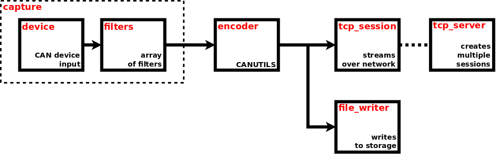
Snippet of CAN capture configuration (at JSON pointer /can/captures/capt0)
{
  "enabled": true,
  "capture": {
    "device": "jcan1",
    "filters_enabled": true,
    "filters": [
      {
        "data": [0, 1, 0, 1],
        "data_mask": [255, 255, 255, 255],
        "ext": false,
        "fd": false,
        "id": 2046,
        "id_mask": 2047,
        "rtr": false,
        "trigger_source": false
      },
      {
        "data": [0, 0, 0, 0, 0, 0, 0, 2],
        "data_mask": [0, 0, 0, 0, 0, 0, 0, 255],
        "ext": true,
        "fd": false,
        "id": 536870910,
        "id_mask": 536870911,
        "rtr": false,
        "trigger_source": false
      }
    ],
    "activity_timer": {
      "enabled": false,
      "arm_on_enable": false,
      "period": 10000,
      "trigger_sources": {
        "arm_on_enable": false,
        "arm_on_message": false,
        "shot": false
      }
    }
  },
  "encoder": {
    "canutils": {
      "timestamp": {
        "type": "monotonic"
      }
    },
    "type": "canutils"
  },
  "file_writer": {
    "enabled": false,
    "path": "mounts:/satadisk/can/captures/capt0/"
  },
  "tcp_server": {
    "port": 51001
  },
  "tcp_session": {}
}
Snippet of CAN capture status (at JSON pointer /can/captures/capt0)
{
  "running": true,
  "capture": {
    "activity_timer": {
      "armed": false,
    }
  }
  "file_writer": {
    "running": false
  }
  "stats": {
    "data": {
      "capture": {
        "passed": 567
        "dropped": 0
      }
    }
  }
}
To enable the CAN capture device, just set enabled to true. See running property in status to get the real state of CAN capture device. If the running property is set to true, then capture, encoder and tcp_server are also running. Element file_writer has its own separate enable property. To have the running CAN capture device, some conditions must be met. Primarily the used physical CAN device must be enabled and must be in error_active state. Each received CAN message is timestamped. Natively the Monotonic time is used as the time base, although it may be converted to System time before presenting (via network or storage) to user. The type of presented timestamp can usually be selected in encoder configuration.
The capture element is the first one in the pipeline. It is the element, where all CAN messages are coming from. The actual physical CAN device used for capturing the messages is specified by device. It may be one of the CAN devices found at JSON pointer /can/devices. Then, if filters_enabled is set to true, the captured CAN message is going to filters, otherwise it is directly going to encoder.
The filters array contains filters, each one successively (in given order) applied on captured CAN message. If any filter matches, the remaining ones are not evaluated and the message passes. If filters array is empty, then no message passes. Each filter may contain multiple critera and if all of them match, then the filter matches. The only required criterion is id (CAN message identifier).
id - CAN message identifier. Should be between 0 and 2047 (0x7FF) for standard 11-bit identifier (CAN 2.0A), or between 0 and 536870911 (0x1FFFFFFF) for extended 29-bit identifier (CAN 2.0B).
id_mask - CAN message identifier mask. If omitted, then defaults to 536870911 (0x1FFFFFFF).
data - CAN message data. Array of bytes, each between 0 and 255 (0xFF). Should be of the same size as the message expected on the bus, between 0 and 8 for non-FD, or between 0 and 8, 12, 16, 20, 24, 32, 48 or 64 for FD messages. If omitted, then filtering by this criterion is disabled.
data_mask - CAN message data mask. Array of bytes. Must be of the same size as CAN message data. If omitted, then defaults to array of 255 (0xFF).
ext - CAN message 'Extended' flag. If omitted, then filtering by this criterion is disabled.
fd - CAN message 'FD' flag. If omitted, then filtering by this criterion is disabled.
rtr - CAN message 'Remote Transmission Request' flag. If omitted, then filtering by this criterion is disabled.
The following pseudocode shows the process of filter critera matching:
 match = ((message.id BITWISE_AND filter.id_mask) EQUALS (filter.id BITWISE_AND filter.id_mask))
     AND (NOT EXISTS filter.data OR ((message.data BITWISE_AND filter.data_mask) EQUALS (filter.data BITWISE_AND filter.data_mask)))
     AND (NOT EXISTS filter.ext OR message.ext EQUALS filter.ext)
     AND (NOT EXISTS filter.fd OR message.fd EQUALS filter.fd)
     AND (NOT EXISTS filter.rtr OR message.rtr EQUALS filter.rtr)
Each filter is able to act as trigger source within the Trigger system. To enable this feature just set trigger_source of appropriate filter to true. Only the first matched filter causes generating trigger, the remaining filters are not evaluated at all. To avoid the unintentional overload of trigger system enable the trigger source only if really required. Identifier of generated trigger is /can/captures/<name>/capture/filters/<index>.
The activity_timer element configures the timer, that just measures the time from the last activity on capture device. It can be used to detect the initial (in)activity on capture device. Set enabled property to enable (not arm, just enable) the timer. When the timer is not armed yet, any passed CAN message arms it. When the timer is armed already, any passed CAN message re-arms it and thus prevents its expiration. When arm_on_enable property is true, the timer gets armed also by each transition to enabled state. See the boolean status property armed to get the real armed state. When the timer is armed (is counting) and reaches the value (in milliseconds) contained in period property (no CAN message arrived in the meantime), it expires (shots) and disarms. The timer is able to act as trigger source within the Trigger system. To enable this feature just set the required trigger source type within the trigger_sources property.
The arm_on_enable type generates trigger whenever the timer gets armed on enabling. The identifier is /can/captures/<name>/capture/activity_timer/arm_on_enable.
The arm_on_message type generates trigger whenever the timer gets armed (not re-armed) by passed CAN message. The identifier is /can/captures/<name>/capture/activity_timer/arm_on_message. This trigger source can be used to detect the initial activity on capture device.
The shot type generates trigger whenever the timer expires (shots). The identifier is /can/captures/<name>/capture/activity_timer/shot. This trigger source can be used to detect the initial inactivity on capture device.
The encoder element is responsible for encoding the proprietary stream of CAN messages into any well known format. The common attribute of all supported encoders is the fact, that encoded stream has no special header or footer. It basically means, that CAN messages can be decoded from any point of running stream, of course usually from boundary of individual messages. Each supported encoder has its own configuration element and the actually selected encoder is determined by type. Currently there is only one supported encoder type: canutils.
canutils
This format is used by can-utils, a well known linux project providing various SocketCAN userspace utilities and tools (see here for detailed description). Basically there are two types of format used by can-utils, compact and long. Currently only compact type is supported. The type of presented timestamp is determined by property timestamp/type, whose possible value is monotonic or system.
Snippet of encoded stream containing these 5 CAN messages (transmitted with 1 second period)
(0000012300.000000) jcan1 100#0011223344556677
(0000012301.000000) jcan1 00000100#0011223344556677
(0000012302.000000) jcan1 100##40011223344556677
(0000012303.000000) jcan1 100##50011223344556677
(0000012304.000000) jcan1 100#R8The file_writer element is responsible for storing the encoded stream to mounted device (e.g. SATA or USB disk). Destination file is determined by path, which is a string complying with definition of URI (Uniform Resource Identifier), see RFC3986. Only scheme and path components are used within the URI.
Scheme component must always be set to mounts value. It means that one of the mounted devices will be used for writing the file.
Path component represents the file path. It must always start with forward slash character "/". The first segment of the path must always be the name of specific mount point, in general it can be any of mount points located in status at JSON pointer /storage/mounts. See Mounts chapter for detailed description. The following segments represent the rest of the file path within the mount point. The path may contain some special variables, which are replaced by their real values at the time the file is created. These variables must be specified in form $(variable_name). Currently supported variables:
time - system time complying with full date and time according to ISO 8601, with milliseconds
ext - default file extension (including the dot ".") corresponding with used data format
When the path ends with forward slash character "/", it is considered as directory and the file name is constructed automatically as $(time)$(ext). When the path contains non-existent directories, they will be created automatically.
Here are examples of possible paths:
mounts:/satadisk/can/captures/capt0/The file is created on storage device, that is mounted to mount point satadisk. Directories can, captures and capt0 are created automatically if they don't exist. Because the path ends with "/", it is considered as directory and the file name is constructed automatically. So the resulting file name on the mounted device may look something like /can/captures/capt0/20240215T105231.517Z.log.
mounts:/satadisk/captures/capt0_$(time)$(ext)The file is created on storage device, that is mounted to mount point satadisk. Directory captures is created automatically if it doesn't exist. The resulting file name on the mounted device may look something like /captures/capt0_20240215T105231.517Z.log.
To enable the file writer, just set enabled to true. See running property in status to get the real state of file writer. To have the running file writer, some conditions must be met. E.g. the whole CAN capture device must be enabled, file writer must be enabled, mount point must exist, mounted device must be writable and must contain enough free space, file name must be correctly specified, used physical CAN device must be enabled. When any of these conditions are not met or any errors occur, the file writer stops working and the running state is set to false. Whenever the file writer changes its running state to true, it creates new file and opens it for writing. When the file writer changes its running state to false, it also closes the file.
Encoded stream may also be transmitted over network as TCP stream. Element tcp_server represents the TCP server, that listens on specified port. Each time it accepts incoming connection, new TCP session is created. Up to 8 TCP sessions may exist at the same time. Each created TCP session is configured with parameters found in tcp_session element. Actually this element is empty object as there is nothing to be configured for now.
When the CAN capture pipeline is running, some useful statistics are being computed. They are available in stats/data status element. Currently only statistics for Capture device are computed. They are avaliable in stats/data/capture status element. The element is present only if the CAN capture pipeline is running.
capture/passed - Number of CAN messages, that were passed through the capture device. It is counted from the time at which the CAN capture pipeline switched to running state.
capture/dropped - Number of CAN messages, that couldn’t be passed through the capture device (e.g. it was busy) and thus were dropped. It is counted from the time at which the CAN capture pipeline switched to running state.
Get status of CAN capture device capt0
curl -v -X GET 'http://192.168.1.200/api/app/status/can/captures/capt0'Enable the CAN capture device capt0
curl -v -X PUT -H 'Content-Type: application/json' -d 'true' 'http://192.168.1.200/api/app/config/can/captures/capt0/enabled'Read the encoded stream of CAN messages from port 51001 (assume that there is listening CAN capture TCP server)
nc 192.168.1.200 51001Get list of files contained in specifed directory and then read the content of selected file
curl http://192.168.1.200/api/fs/mounts/satadisk/can/captures/capt0/
curl http://192.168.1.200/api/fs/mounts/satadisk/can/captures/capt0/20240216T110003.165Z.logTimers are simple devices, that allow to perform any predefined operation (via Trigger system) after the specified period expires. They are also User-managed devices, so their count, naming and life cycle are fully controlled by user. Configuration and status are located at JSON pointer /timer.
Snippet of timers configuration (at JSON pointer /timer)
{
  "devices": {
    "t0": {
      "arm_on_enable": false,
      "enabled": false,
      "periods": [500, 1000, 2000],
      "shots_count_max": 0,
      "trigger_sources": {
        "shot": false,
        "shot_number": false,
        "shot_period": false
      }
    },
    "t1": {
      "arm_on_enable": false,
      "enabled": false,
      "periods": [0, 1000],
      "shots_count_max": 0,
      "trigger_sources": {
        "shot": false,
        "shot_number": false,
        "shot_period": false
      }
    }
  }
}
Snippet of timers status (at JSON pointer /timer)
{
  "devices": {
    "t0": {
      "armed": false,
      "arms_count": 0,
      "shots_count": 0
    },
    "t1": {
      "armed": false,
      "arms_count": 0,
      "shots_count": 0
    }
  }
}
To work with timer it must be enabled first, just set the enabled property to true. When the timer is enabled, it can be switched between armed and disarmed state. The current state is indicated by armed status property. When property arm_on_enable is true, the timer is armed automatically by transition to enabled state (changing enabled property to true). To manually switch the armed state, just call one of these synchronous nonparametric actions at URL paths.
/api/app/actions/timer/devices/<name>/arm/api/app/actions/timer/devices/<name>/disarmWhen the timer gets armed, it starts counting with milliseconds resolution. Now the property periods comes into the game. It contains the array of periods, in milliseconds, the timer successively counts and after each period is reached, the timer shots (expires). When the last period is reached, the counting continues from the second element of periods array (periods[1]). The first element (periods[0]) is skipped when returning, so it may be used as initial delay.
Let's have periods containing [500,1000,2000]. When the timer gets armed, it shots as follows:
500ms | shot | 1000ms | shot | 2000ms | shot | 1000ms | shot | 2000ms | shot | 1000ms | ...Let's have periods containing [0,1000]. When the timer gets armed, it shots as follows:
shot | 1000ms | shot | 1000ms | shot | 1000ms | ...When the number of shots reaches the value set in shots_count_max property, the timer is disarmed automatically. Set the shots_count_max property to zero to allow infinite counting. The number of shots is indicated by shots_count status property, which is zeroed by transition to armed state. The number of transitions to armed state is indicated by arms_count status property, which is zeroed by transition to enabled state.
The timer gets armed (counting starts) on either of following conditions:
/api/app/actions/timer/devices/<name>/arm is called while property enabled is trueThe timer gets disarmed (counting stops) on either of following conditions:
/api/app/actions/timer/devices/<name>/disarm is calledEach timer is able to act as trigger source within the Trigger system. To enable this feature just set the required trigger source type within the trigger_sources property. To avoid the unintentional overload of trigger system enable only those trigger sources, that are really required. There exist three types of trigger sources, each one generates exactly one trigger per one timer shot.
The shot type generates triggers, whose identifier is /timer/devices/<name>/shot.
The shot_number type generates triggers, whose identifier is /timer/devices/<name>/shot/number/<value>. The <value> identifies the shot number, it equals the shots_count status property.
The shot_period category generates triggers, whose identifier is /timer/devices/<name>/shot/period/<value>. The <value> identifies the shot period, it equals the index of period in periods array property.
Whenever any configuration property is changed, the timer is disabled internally. Then, when the enabled property is set to true, the timer is enabled again. When the timer was armed before configuration change, it will be armed again only if arm_on_enable property is set to true.
Get status of timer device t0
curl -v -X GET 'http://192.168.1.200/api/app/status/timer/devices/t0'Enable timer device t0
curl -v -X PUT -H 'Content-Type: application/json' -d 'true' 'http://192.168.1.200/api/app/config/timer/devices/t0/enabled'Arm timer device t0
curl -v -X POST 'http://192.168.1.200/api/app/actions/timer/devices/t0/arm'This part of API describes the parameters of Digiteq Automotive FG4 PCIe cards. Common FG4 status is available at JSON pointer /fg4. Status of particular devices is available at JSON pointer /fg4/devices. FG4 devices are System-managed, so their names are fully controlled by operating system. There is no configuration available.
Snippet of FG4 status (at JSON pointer /fg4)
{
  "devices": {
    "001-003-001-018": {...},
    "001-031-002-072": {...},
    "001-031-002-099": {...}
  }
}
Snippet of FG4 device status (at JSON pointer /fg4/devices/001-003-001-018)
{
  "address": "0000:06:00.0",
  "vendor_id": 7896,
  "device_id": 257,
  "product_id": 1,
  "fw_type": "fpdl3",
  "fw_version": 814,
  "module_type": "fpdl3",
  "module_version": 1,
  "serial_number": "001-003-001-018",
  "temperature": 52,
  "video": {
    "captures": [
      "fg4_001-003-001-018_i1",
      "fg4_001-003-001-018_i0"
    ],
    "outputs": [
      "fg4_001-003-001-018_o0",
      "fg4_001-003-001-018_o1"
    ]
  }
}
address - PCI address.
vendor_id - Vendor ID, 7896 (0x1ed8) - Digiteq Automotive.
device_id - Device ID, 257 (0x0101) - T100, 513 (0x0201) - T200.
product_id - Product ID, 1 - T100, 2 - T200.
fw_type - Firmware type (fpdl3, gmsl, gmsl1, recovery, unknown).
fw_version - Firmware version.
module_type - Module type (fpdl3, gmsl_var1, gmsl_var2, gmsl_var3, gmsl_var3_coax, gmsl1_coax, no_module_present, unknown).
module_version - Module version.
serial_number - Serial number.
temperature - Temperature, in degree Celsius.
video/captures - List of video captures. These are the names of video capture devices available on module..
video/outputs - List of video outputs. These are the names of video output devices available on module.
All these parameters are specific for alone FG4 PCIe card, no matter which (if ever) module is inserted. The configuration and status parameters of particular video capture/output devices (dependent on inserted module) are part of video capture/output streaming subsystem. It is available at JSON pointers /video/captures/<name>/capture/fg4 and /video/outputs/<name>/output/fg4, where the <name> corresponds to the name available in list at JSON pointer /fg4/devices/*/video/captures and /fg4/devices/*/video/outputs. See Video captures and Video outputs for detailed information about video capture/output streaming subsystem.
Each FG4 PCIe card must contain firmware, which is compatible with used FG4 Multibox and also with the type of inserted module. FG4 Multibox tries to satisfy this requirement automatically, see FG4 card firmware update for detailed information.
Mainboard PMIC (Power Management IC) is an integrated circuit located on Mainboard. It controls the onboard power supply, power on/off sequences and also external triggers. It also provides the ability to automatically power-on the FG4 Multibox, either when it gets connected to power supply or when configured event occurs on external trigger or when configured message is received on CAN bus. The configuration and status are located at JSON pointer /mbpmic.
Snippet of maiboard PMIC configuration (at JSON pointer /mbpmic)
{
  "poweron": false,
  "triggers": {
    "tr1": {
      "edge": "none",
      "pull": "none",
      "wake": false
    },
    "tr2": {
      "edge": "none",
      "pull": "none",
      "wake": false
    }
  },
  "can": {
    "devices": {
      "can1": {
        "enabled": true,
        "bitrate": 500000,
        "data_bitrate": 2000000,
        "sample_point": 0.75,
        "data_sample_point": 0.75,
        "wake_trigger": {
          "enabled": true,
          "id": 1,
          "id_mask": 2047,
          "ext": false,
          "data": [1, 2, 3, 4],
          "data_mask": [127, 127, 127, 127]
        }
      },
      "can2": {
        "enabled": false,
        "bitrate": 500000,
        "data_bitrate": 2000000,
        "sample_point": 0.75,
        "data_sample_point": 0.75,
        "wake_trigger": {
          "enabled": false,
          "id": 0,
          "id_mask": 0,
          "ext": false,
          "data": [],
          "data_mask": []
        }
      }
    }
  }
}
Snippet of maiboard PMIC status (at JSON pointer /mbpmic)
{
  "monitor": {
    "fanrpm": 1234,
    "tmb": 35,
    "tmcu": 36,
    "vin": 18837,
    "vinb": 18946
  },
  "wake_source": "pwrbtn",
  "version": "1.1.6",
  "git_hash": 0x045C6CC5,
  "can": {
    "devices": {
      "can1": {
        "running": true,
        "bitrate": 500000,
        "data_bitrate": 2000000,
        "sample_point": 0.75,
        "data_sample_point": 0.75,
        "wake_trigger": {
          "enabled": true
        }
      },
      "can2": {
        "running": false,
        "bitrate": 500000,
        "data_bitrate": 2000000,
        "sample_point": 0.75,
        "data_sample_point": 0.75,
        "wake_trigger": {
          "enabled": false
        }
      }
    },
    "wake_message": {
      "device": "can1",
      "id": 1,
      "ext": false,
      "rtr": false,
      "dlc": 4,
      "data": [1, 2, 3, 4]
    }
  }
}The boolean property poweron controls the behavior of FG4 Multibox after the power supply is connected. If false, then it remains in power-off state. If true, then the power-on sequence is started automatically. For example this may be useful for automatic restoration of function after accidental power cut.
The object triggers controls the External triggers TR1 and TR2. The property edge (none, rising, falling or both) configures the type of edge causing the trigger event. Set to none to disable the trigger. The property pull (none, up or down) configures the connection of internal pull-up or pull-down resistor. Set to none to have no pull resistor connected. The boolean property wake allows to power-on the FG4 Multibox when configured trigger event occurs. Set to false to disable this feature. Triggers TR1 and TR2 also act as trigger sources within the Trigger system. Identifiers of generated triggers are /mbpmic/tr1 and /mbpmic/tr1.
The mainboard PMIC contains two CAN devices, that are connected to the CAN buses 1 and 2. Device can1 is connected to the CAN bus 1 and device can2 is connected to the CAN bus 2. These devices always work in passive mode, so they neither transmit nor acknowledge. These devices internally work in FD mode, so both data_bitrate and data_sample_point must be set. When using on non-FD CAN bus, just set data_bitrate to the same value as bitrate and data_sample_point to the same value as sample_point.
enabled - Set to true to enable the CAN device.
bitrate - Bit rate, in bits per second from 1000 to 1000000.
data_bitrate - Data bit rate, in bits per second. May be set continuously from 1000 to 3750000, then only by discrete levels (4000000). Must be equal or greater than bitrate.
sample_point - Sample point, in percentage from 0.0 to 0.990.
data_sample_point - Data sample point, in percentage from 0.0 to 0.990.
In some rare cases the given combination of configuration values cannot be used, especially it relates to bitrates. See status to get actually used values and whether the CAN device is really running.
Each CAN device is able to wake-up the FG4 Multibox on reception of specific CAN message. When the received message passes the configured filter (we say there is a match), then the FG4 Multibox wakes-up. When the wake-up functionality is required, then both the device (can/<name>/enabled) and wake_trigger (can/<name>/wake_trigger/enabled) must be enabled in configuration! See status to find out whether the device (can/<name>/running) is really running and wake_trigger (can/<name>/wake_trigger/enabled) is really enabled. Also you can check the Power button LED to see if the wake-up trigger is really active (waiting for specific CAN message). When the FG4 Multibox is off and wake-up trigger is active, then the LED should be blue. The wake-up functionality is configured by wake_trigger element.
enabled - Set to true to enable the wake-up trigger.
id - CAN message identifier. Should be between 0 and 2047 (0x7FF) for standard 11-bit identifier (CAN 2.0A), or between 0 and 536870911 (0x1FFFFFFF) for extended 29-bit identifier (CAN 2.0B).
id_mask - CAN message identifier mask.
data - CAN message data. Array of bytes, each between 0 and 255 (0xFF). Should be of the same size as the message expected on the bus, between 0 and 8 for non-FD, or between 0 and 8, 12, 16, 20, 24, 32, 48 or 64 for FD messages. If empty, then filtering by this criterion is disabled.
data_mask - CAN message data mask. Array of bytes. Must be of the same size as CAN message data.
ext - CAN message 'Extended' flag.
The following pseudocode shows the process of filter critera matching:
 match = ((message.id BITWISE_AND filter.id_mask) EQUALS (filter.id BITWISE_AND filter.id_mask))
     AND (EMPTY filter.data OR ((message.data BITWISE_AND filter.data_mask) EQUALS (filter.data BITWISE_AND filter.data_mask)))
AND (message.ext EQUALS filter.ext)NOTE:
At the time of releasing this firmware version, all so far manufactured FG4 Multibox products contain a hardware bug, that causes the wake-up trigger is working only on can2 device. Although the user is able to enable the can1 wake-up trigger, although the Power button LED indicates it is really active (blue light), FG4 Multibox will not wake-up via can1 device.
When the FG4 Multibox is woken-up by a CAN message (wake_source in status is can1 or can2), then extra element can/wake_message exists in status. It contains properties of the waking message.
device - CAN device the waking message was received on, can1 or can2
id - CAN message identifier
ext - CAN message 'Extended' flag
rtr - CAN message 'Remote Transmission Request' flag
dlc - CAN message 'Data Length Code'
data - CAN message data
The status element wake_source shows the source caused the wake-up (power-on) of FG4 Multibox, it may be one of
n/a - not available (should not occur)
pwron - power supply was connected (should occur only if poweron is true)
pwrbtn - power button was pressed
pwrc - power-cycle was requested
tr1 - configured event occurred on external trigger TR1
tr2 - configured event occurred on external trigger TR2
can1 - configured message received by mainboard PMIC can1
can2 - configured message received by mainboard PMIC can2
bootldr - requested by mainboard PMIC bootloader (may occur after PMIC firmware is updated)
The status element monitor shows values from some internal sensors.
fanrpm - cooling fan speed, in rotations per second
tmb - mainboard temperature, in degree Celsius
tmcu - PMIC temperature, in degree Celsius
vin - input voltage, in millivolts
vinb - input backup voltage, in millivolts
Property version shows the version of mainboard PMIC firmware.
Property git_hash shows the git commit hash of mainboard PMIC firmware source.
Trigger system allows to perform a specific operation as a reaction to a specific event. Now some terms must be introduced to avoid possible ambiguous understanding. Object that generates the trigger is called trigger source. Object that consumes the trigger is called trigger sink. Object that is generated by trigger source and is consumed by trigger sink is called trigger. Trigger source represents a place, where an event may be generated. This event is called trigger. Through a configurable connection matrix the event may arrive to any trigger sink. Trigger sink represents a place, where any event may be consumed by performing a specified operation/reaction. Trigger system configuration and status are located at JSON pointer /trigger.
Snippet of trigger system configuration (at JSON pointer /trigger)
{
  "connections": {},
  "file_writer": {
    "enabled": false,
    "path": "mounts:/satadisk/triggers/"
  },
  "tcp_server": {
    "port": 51000
  },
  "timestamp": {
    "type": "monotonic"
  }
}
Snippet of trigger system status (at JSON pointer /trigger)
{
  "file_writer": {
    "running": false
  }
}Trigger (event) is an object generated by trigger source. Each trigger has two attributes, identifier and timestamp. Identifier determines the trigger source, that generated the trigger. Timestamp determines the moment in time the trigger was generated. Natively the Monotonic time is used as the time base, although it may be converted to System time before presenting (via network or storage) to user. The type of presented timestamp is determined by property timestamp/type, whose possible value is monotonic or system. Triggers may be written to storage or streamed over network. In both cases they are transferred as a stream of newline delimited JSON objects, known as NDJSON. Each JSON object is described by this schema:
{
    "$schema" : "http://json-schema.org/draft-07/schema#",
    "type" : "object",
    "properties" : {
        "id" : {
            "title" : "Trigger identifier",
            "description" : "Trigger identifier determines the trigger source, that generated the trigger.",
            "type" : "string"
        },
        "ts" : {
            "title" : "Trigger timestamp",
            "description" : "Trigger timestamp determines the moment in time the trigger was generated, in nanoseconds.",
            "type" : "integer"
        }
    },
    "required" : ["id", "ts"]
}
The stream of triggers, either written to storage or received via network, may look something like:
{"id":"/mbpmic/tr1","ts":3961704067701}
{"id":"/control/tcp_session/tr0","ts":3962698000787}
{"id":"/can/captures/capt0/capture/filters/0","ts":3963809236439}
{"id":"/timer/devices/t0/shot","ts":3964894626995}Trigger source represents a place, where triggers (events) are generated. Each trigger source has its own unique identifier. Identifiers of existing trigger sources:
/video/captures/<name>capture/fg4/signal/change/on
/video/captures/<name>capture/fg4/signal/change/off
These trigger sources generate their triggers whenever a change of video signal occurs on input of FG4 capture device. Value on means, that immediately after the change a valid video signal was detected. Value off means, that immediately after the change no valid video signal was detected. See Trigger sources for detailed decription.
/can/captures/<name>/capture/filters/<index>
This trigger source generates its trigger whenever a CAN message received on capture <name> matches filter <index>. See Filters for detailed description.
/can/captures/<name>/capture/activity_timer/arm_on_enable
/can/captures/<name>/capture/activity_timer/arm_on_message
/can/captures/<name>/capture/activity_timer/shot
These trigger sources generate their triggers whenever a specific event occurs on activity timer of CAN capture <name>. See Activity timer for detailed description.
/trigger/tcp_session/<arg>
This trigger source generates its trigger whenever a specific message is received via trigger TCP session. It is the same session as the one created for streaming triggers over network, see Streaming over network. The message must be a newline delimited JSON (NDJSON) of type string, whose value determines the arg component of the trigger source name. So if "tr" message is received, then trigger source /trigger/tcp_session/tr generates its trigger.
/control/tcp_session/<arg>
This trigger source generates its trigger whenever a dedicated action is called via remote API served by application service. Just call the parametric synchronous action at URL path /api/app/actions/trigger/send to generate the trigger. The parameter contains a custom text (expressed as JSON of type string), that determines the arg component of the trigger source name. So if action /api/app/actions/trigger/send with parameter "tr" is called, then trigger source /control/tcp_session/tr generates its trigger.
/mbpmic/tr1
/mbpmic/tr2
These trigger sources generate their triggers whenever a specified event occurs on external trigger TR1 or TR2. See Mainboard PMIC for detailed description.
/timer/devices/<name>/shot
/timer/devices/<name>/shot/number/<value>
/timer/devices/<name>/shot/period/<value>
These trigger sources generate their triggers whenever a timer <name> expires. See Timers for detailed description.
Trigger sink represents a place, where triggers (events) are consumed, where specified reactions are performed. There are two types of sinks, configuration and action. Both sinks allow to perform any operation, that can also be performed via remote API served by Application service. Configuration sink allows to manipulate the configuration available at URL path /api/app/config, see Application service configuration. Action sink allows to call any action at URL path /api/app/actions/*, see Application service actions. It just invokes the specified action, without waiting for results, so it can be used for all types of actions (parametric/nonparametric, synchronous/asynchronous). See Connections to see how to use trigger sinks.
The file_writer element is responsible for storing the generated triggers to mounted device (e.g. SATA or USB disk). Destination file is determined by path, which is a string complying with definition of URI (Uniform Resource Identifier), see RFC3986. Only scheme and path components are used within the URI.
Scheme component must always be set to mounts value. It means that one of the mounted devices will be used for writing the file.
Path component represents the file path. It must always start with forward slash character "/". The first segment of the path must always be the name of specific mount point, in general it can be any of mount points located in status at JSON pointer /storage/mounts. See Mounts chapter for detailed description. The following segments represent the rest of the file path within the mount point. The path may contain some special variables, which are replaced by their real values at the time the file is created. These variables must be specified in form $(variable_name). Currently supported variables:
time - system time complying with full date and time according to ISO 8601, with milliseconds
ext - default file extension (including the dot "."), currently it is always .ndjson
When the path ends with forward slash character "/", it is considered as directory and the file name is constructed automatically as $(time)$(ext). When the path contains non-existent directories, they will be created automatically.
Here are examples of possible paths:
mounts:/satadisk/triggers/The file is created on storage device, that is mounted to mount point satadisk. Directory triggers is created automatically if it doesn't exist. Because the path ends with "/", it is considered as directory and the file name is constructed automatically. So the resulting file name on the mounted device may look something like /triggers/20240215T105231.517Z.ndjson.
mounts:/satadisk/triggers_$(time)$(ext)The file is created on storage device, that is mounted to mount point satadisk. The resulting file name on the mounted device may look something like /triggers_20240215T105231.517Z.ndjson.
To enable the file writer, just set enabled to true. See running property in status to get the real state of file writer. To have the running file writer, some conditions must be met. E.g. the file writer must be enabled, mount point must exist, mounted device must be writable and must contain enough free space, file name must be correctly specified. When any of these conditions are not met or any errors occur, the file writer stops working and the running state is set to false. Whenever the file writer changes its running state to true, it creates new file and opens it for writing. When the file writer changes its running state to false, it also closes the file.
Generated triggers may also be transmitted over network as TCP stream. Element tcp_server represents the TCP server, that listens on specified port. Each time it accepts incoming connection, new TCP session is created. Up to 8 TCP sessions may exist at the same time.
The connections object contains connections between trigger sources and trigger sinks. Multiple trigger sinks may be connected to single trigger source. When trigger source generates a trigger (an event occurs), all connected trigger sinks consume it (an reaction happens). Each object in connections represents connection between single trigger source and multiple trigger sinks. The object name specifies trigger source identifier, the object value specifies an array of connected trigger sinks. Each trigger sink contain one single child object, whose name determines the type of trigger sink. Currently there are two possible types, configuration (named as config) and action (named as action).
Snippet of trigger connections configuration (at JSON pointer /trigger/connections)
{
  "/control/tcp_session/tr0": [
    {
      "config": {
        "operation": {
          "arg": false,
          "name": "replace"
        },
        "path": "/video/captures/fg4_001-003-001-018_i0/enabled"
      }
    }
  ],
  "/control/tcp_session/tr1": [
    {
      "config": {
        "operation": {
          "arg": {
            "enabled": true,
            "sinks": {
              "video": {
                "enabled": true,
                "file_writer": {
                  "enabled": true
                }
              }
            }
          },
          "name": "modify"
        },
        "path": "/video/captures/fg4_001-003-001-018_i0"
      }
    }
  ],
  "/control/tcp_session/tr2": [
    {
      "config": {
        "operation": {
          "name": "negate"
        },
        "path": "/video/captures/fg4_001-003-001-018_i0/enabled"
      }
    }
  ],
  "/control/tcp_session/tr3": [
    {
      "action": {
        "arg": {
          "text": "tr3",
          "timeout": 1000
        },
        "name": "/video/captures/fg4_001-003-001-018_i0/trigger_mark"
      }
    }
  ],
  "/timer/devices/t0/shot": [
    {
      "action": {
        "arg": {
          "text": "t0",
          "timeout": 250
        },
        "name": "/video/captures/fg4_001-003-001-018_i0/trigger_mark"
      }
    }
  ]
}Configuration trigger sink allows to manipulate the configuration available at URL path /api/app/config, see Application service configuration. It behaves the similar way as via HTTP API, any JSON nodes may be changed, created, deleted, etc. Configuration trigger sink is contained in object named as config. It contains two required items, path and operation. The path is of type string and contains JSON pointer to the configuration node, that should be manipulated. The operation is of type object and contains one required item name and one optional item arg. The presence and content of arg depends on operation name. This is the way how the configuration trigger sink works, an operation (specified by name) is performed on configuration JSON node (specified by path). Supported operation names:
replace - replaces content of existing node (at JSON pointer path) by content of arg. It works the same way as PUT verb in HTTP API.
modify - modifies/patches content of existing node (at JSON pointer path) by using content of arg. The content of arg is considered as JSON patch, see RFC6902. It works the same way as PATCH verb in HTTP API.
create - creates new node (if doesn't exist) at JSON pointer path. The last segment of path is used as name of node to be created. The previous segments must point to existing nodes. The content of arg is used as content of the new node. It works the same way as CREATE verb in HTTP API.
delete - deletes existing node (if exists) at JSON pointer path. The last segment of path is used as name of node to be deleted. The previous segments must point to existing nodes. The arg is not used. It works the same way as DELETE verb in HTTP API.
negate - negates value at JSON pointer path. The value must be of boolean type. The arg is not used. There is no counterpart verb in HTTP API.
Basically there are two methods how to set multiple properties as a reaction to single trigger. First, each property is set (by replace) in separate sink and these sinks are the separate members of trigger sink array. Second, all properties are part of single JSON patch, which is then used (by modify) in one single trigger sink. Always prefer the second method as it is much more efficient.
For better understanding let's go through the above snippet of trigger connections. There are three configuration trigger sinks, each connected to different trigger source.
First trigger sink is connected to trigger source /control/tcp_session/tr0. The trigger source generates its trigger whenever action /trigger/send is called with argument "tr0". As a reaction, trigger sink sets the configuration property /video/captures/fg4_001-003-001-018_i0/enabled to false. It means, that the video capture device fg4_001-003-001-018_i0 will be disabled.
Second trigger sink is connected to trigger source /control/tcp_session/tr1. The trigger source generates its trigger whenever action /trigger/send is called with argument "tr1". As a reaction, multiple configuration properties are set at the same time. Properties /video/captures/fg4_001-003-001-018_i0/enabled, /video/captures/fg4_001-003-001-018_i0/sinks/video/enabled and /video/captures/fg4_001-003-001-018_i0/sinks/video/file_writer/enabled are set to true. It means, that the video capture device fg4_001-003-001-018_i0 will be enabled, its video sink will be enabled and the file writer of this video sink will also be enabled.
Third trigger sink is connected to trigger source /control/tcp_session/tr2. The trigger source generates its trigger whenever action /trigger/send is called with argument "tr2". As a reaction, trigger sink negates (switches) the configuration property /video/captures/fg4_001-003-001-018_i0/enabled.
Action trigger sink allows to call any action at URL path /api/app/actions/*, see Application service actions. It behaves the similar way as via HTTP API, any action with any argument may be called. It just invokes the specified action, without waiting for results, so it can be used for all types of actions (parametric/nonparametric, synchronous/asynchronous). Action trigger sink is contained in object named as action. It contains one required item name and one optional item arg. The presence and content of arg depends on name. This is the way how the action trigger sink works, it calls the action (specified by name) with argument (specified by arg).
For better understanding let's go through the above snippet of trigger connections. There are two action trigger sinks, each connected to different trigger source.
First trigger sink is connected to trigger source /control/tcp_session/tr3. The trigger source generates its trigger whenever action /trigger/send is called with argument "tr3". As a reaction, trigger sink calls the action /video/captures/fg4_001-003-001-018_i0/trigger_mark with argument {"text": "tr3","timeout": 1000}. It means, that a trigger mark tr3 will be rendered in video capture stream for 1000 milliseconds.
Second trigger sink is connected to trigger source /timer/devices/t0/shot. The trigger source generates its trigger whenever timer device t0 expires. As a reaction, trigger sink calls the action /video/captures/fg4_001-003-001-018_i0/trigger_mark with argument {"text": "t0","timeout": 250}. It means, that a trigger mark t0 will be rendered in video capture stream for 250 milliseconds.
Get status of trigger system
curl -v -X GET 'http://192.168.1.200/api/app/status/trigger'Get configuration of trigger connections
curl -v -X GET 'http://192.168.1.200/api/app/config/trigger/connections'Read the stream of triggers from dedicated trigger TCP session on port 51000
nc 192.168.1.200 51000Generate trigger /trigger/tcp_session/tr by dedicated trigger TCP session on port 51000
echo '"tr"' | nc -N 192.168.1.200 51000Generate trigger /control/tcp_session/tr by calling of dedicated action via HTTP API
curl -v -X POST -H 'Content-Type: application/json' -d '"tr"' 'http://192.168.1.200/api/app/actions/trigger/send'Get list of files contained in specifed directory and then read the content of selected file
curl http://192.168.1.200/api/fs/mounts/satadisk/triggers/
curl http://192.168.1.200/api/fs/mounts/satadisk/triggers/20240314T111001.479Z.ndjsonThis part of API deals with graphics card outputs and connected displays. Status is located at JSON pointer /screen. Configuration is not available.
Snippet of screen status (at JSON pointer /screen)
{
  "outputs": {
    "HDMI-0": {
      "connected": true,
      "mode": {
        "pclk": 241545000,
        "hdisp": 1440,
        "hsyncstart": 2608,
        "hsyncend": 2640,
        "htotal": 2720,
        "vdisp": 2560,
        "vsyncstart": 1443,
        "vsyncend": 1448,
        "vtotal": 1481,
        "flags": [
          "hsyncpos",
          "vsyncpos"
        ]
      }
    }
  }
}
The element outputs contains all existing outputs of the embedded graphics card. Each output then contains information about its current configuration. Property connected indicates, whether the output is connected (e.g. to external display). If the output is connected and if certain timing mode is selected, then property mode is present and contains the selected modeline timing parameters.
pclk - Pixel clock in Hz.
hdisp - Horizontally visible area in number of pixels (clock ticks). Effectively it represents the horizontal resolution of the connected display.
hsyncstart -
hsyncend -
htotal -
vdisp - Vertically visible area in number of lines. Effectively it represents the vertical resolution of the connected display.
vsyncstart -
vsyncend -
vtotal -
flags - List of additional flags. It may contain one or more of these values: hsyncpos, hsyncneg, vsyncpos, vsyncneg, interlace, doublescan, csync, csyncpos, csyncneg
Horizontal and vertical frequencies can be computed as follows:
hfreq = pclk/htotal
vfreq = pclk/(htotal * vtotal)
See Xfree86 Modeline to get more information about modeline timing parameters.
FG4 Multibox contains only one output, named as HDMI-0. When external display is connected, preferred timing mode (based on display's EDID and capabilities of the embedded graphics card) is selected automatically. It may happen, that no suitable mode can be selected, in this case the property mode is not present, although the connected property is true. The output is intended to be used only by GUI.
This part of API deals with desktop, that represents the area shown on display connected to HDMI. See Screen chapter to get detailed information about connected display. Although this part of API is named as GUI, it only supports graphical output. There is no support for keyboard or mouse input. The GUI status is located at JSON pointer /gui. Configuration is not available.
Snippet of GUI status (at JSON pointer /gui)
{
  "desktop": {
    "depth": 24,
    "size": [
      2560,
      1440
    ]
  }
}
Property desktop contains information about current desktop configuration. Property depth contains color depth in bits per pixel, property size contains desktop dimensions [width, height] in pixels. The existence of desktop doesn't depend on existence of connected display. Internally the desktop works permanently, although no display is connected. On the other hand, when display is connected, desktop size is adjusted according to the size of the display. When display is disconnected, desktop size remains unchanged. Before display is connected for the first time after the boot, the initial desktop size is [640, 480].
After the boot a home window is shown. It is a borderless black window with some useful information rendered in the top-left corner. The first line contains current desktop size, the second line contains localized date and time, the remaining lines contain the state and IP addresses assigned to the connected network devices. The home window may be overlapped by another windows, e.g. all video capture and video output devices may have their own preview windows.
CPU related stuff is located at JSON pointer /cpu. Only status is available.
Snippet of CPU status (at JSON pointer /cpu)
{
  "usage": 12,
  "temperature": 44
}
usage - Usage, in percentage, in range from 0 to 100. The usage is computed over all six (2x Denver 2, 4x Cortex-A57) cores. Typical usage of idle state is below 5%.
temperature - Temperature, in degree Celsius.
RAM related stuff is located at JSON pointer /ram. Only status is available.
Snippet of RAM status (at JSON pointer /ram)
{
  "size": {
    "total": 8241074176,
    "used": 1721339904
  }
}
/size/total - Total RAM size, in bytes.
/size/used - Used RAM size, in bytes.
Some general information about FG4 Multibox is located at JSON pointer /about. Only status is available. The information is static, so it never changes when the FG4 Multibox is running.
Snippet of about status (at JSON pointer /about)
{
  "factory_installer_version": "32.5.0.5",
  "factory_package_version": "1.0-build236",
  "runtime_package_version": "1.0-build236",
  "serial_number": "010-001-001-001",
  "jetson_type": "tx2"
}
factory_installer_version - Version of used factory installer. It is the tool, that is used for installation of factory package. See Firmware to get detailed information.
factory_package_version - Version of installed factory package.
runtime_package_version - Version of installed runtime package.
serial_number - Serial number of FG4 Multibox.
jetson_type - Type of Nvidia Jetson module. Possible values: tx2, tx2i.
Graphical interface is implemented by web application, hosted on FG4 Multibox HTTP server, TCP port 80, URL path /www/web/index.html. Actually URL path / may be also used as there exists redirection 301 (moved permanently) to real location. So when using default IP address, just write http://192.168.1.200/ to your favourite web browser. Web application uses the FG4 Multibox API as its backend.
The Dashboard serves as the homepage of the web interface. Its primary purpose is to display the installed FG4 PCIe cards, their interface modules, and their status, as well as the CPU load and memory usage of the FG4 Multibox.
The Dashboard page is divided into several sections, which are described below:
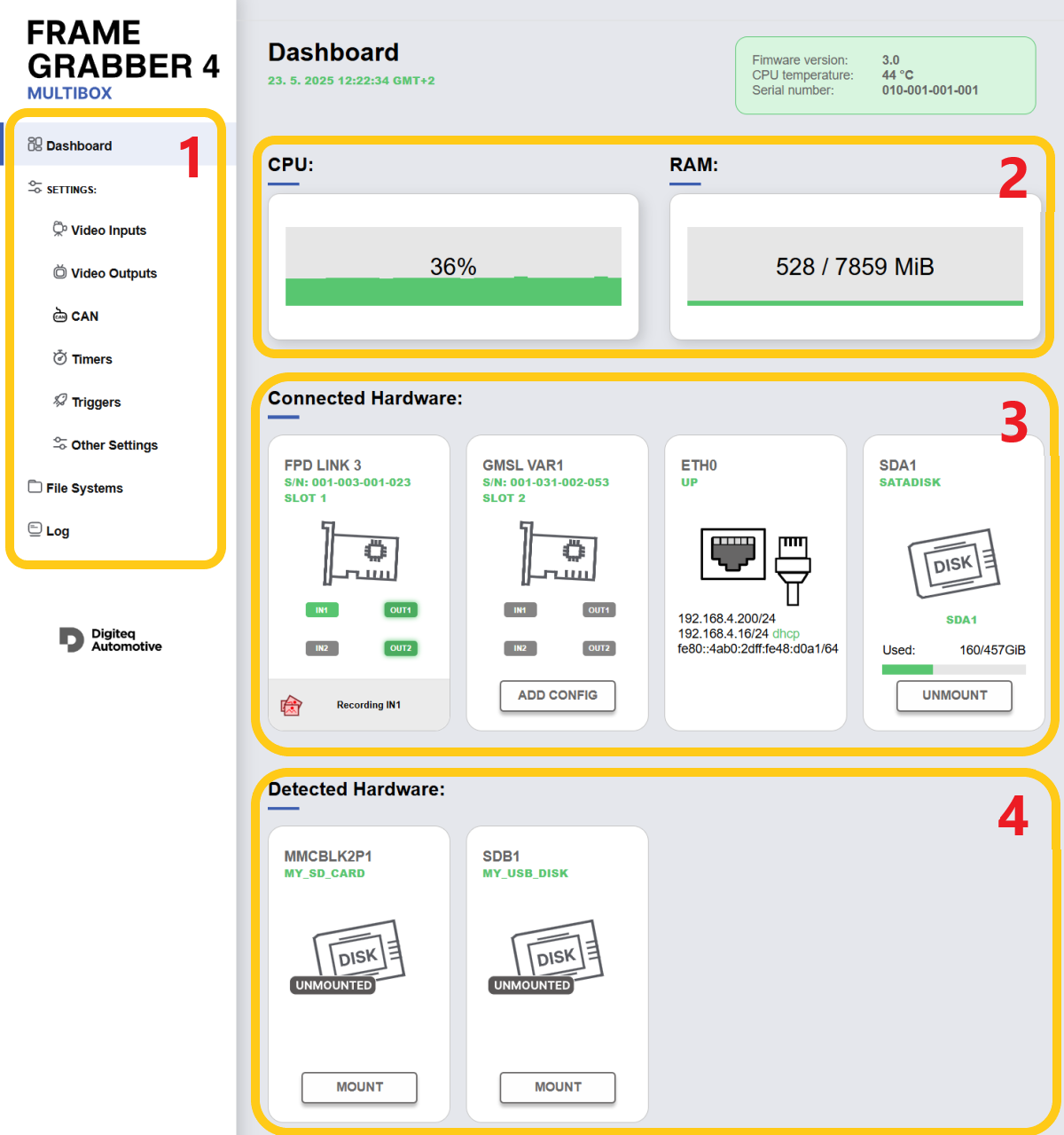
This section provides navigation options to various parts of the web interface. The main menu is displayed on all pages of the interface.
This section shows real-time data on CPU load and memory usage of the FG4 Multibox.
This section lists the FG4 PCIe cards and other hardware currently installed and connected to the system. For FG4 PCIe cards, it displays the status of inputs, outputs, and recording status. For mounted storage devices, clicking on the DISK symbol opens the corresponding storage in File Systems.
When an FG4 PCIe card is inserted into the FG4 Multibox for the first time … (or if no configuration page exists yet), the ADD CONFIG button appears. Pressing ADD CONFIG creates configuration pages for all inputs and outputs associated with the card. These configuration pages are then displayed in the Video Inputs and Video Outputs sections of the main menu.
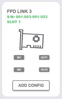
The symbols IN1, IN2, OUT1, and OUT2 use colors to indicate their current system status.
Inputs (IN1, IN2):
Outputs (OUT1, OUT2):
Clicking on the symbol opens the corresponding input or output settings.
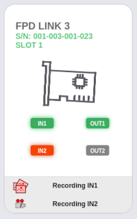
Pictures Symbol: Indicates active picture recording for IN1.

Video Symbol: Indicates that video recording for IN1 is in progress.

Pictures and Video Symbol: Indicates that both picture and video recording for IN1 are active.
Note: Active picture recording is indicated even in the "triggered" mode, where an additional trigger event is required to capture the picture.
This section displays storage devices that have been detected and can be mounted to the file system. Clicking the "MOUNT" button mounts the device under system device names such as sdb1, sdb2, sdc1, etc. Once mounted, the device will move from the "Detected Hardware" section to the "Connected Hardware" section. The mounted devices are then accessible from the "File Systems" section in the main menu. Before physically disconnecting a storage device, it is recommended to unmount it to ensure data integrity.
This page shows the video inputs. Let's go through the sections at the top of the input page:
If a configuration page exists for an input that is no longer present (e.g., if the FG4 PCIe card has been removed), the page remains editable but its settings are not applied. Instead of the slot and input number, it is marked as "UNUSED".
If the FG4 PCIe card and the input exist but the configuration page is missing, an "ADD INPUT CONFIGURATION" button appears. Pressing this button will create the missing configuration pages for all inputs.
Connector location: A graphical representation of the input connector's position on the back of the FG4 Multibox.
The TCP addresses can be selected with a triple-click and then copied to the clipboard.
Input status: Detected timing parameters and calculated framerate of the input video signal.
Input Enable toggle: This switch activates the processing of the signal coming from the input to the FG4 Multibox.
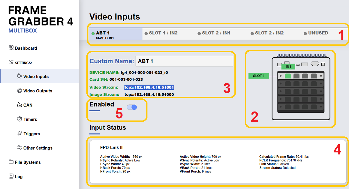
The following sections or individual settings blocks on Video Inputs web page correspond to the Video captures configuration as described in the documentation above. They are listed and named here to match the web interface:
This page shows the video outputs. Let's go through the sections at the top of the input page:
Output configuration list: Shown on all output pages. Outputs are ordered by slot and output number, with custom names (e.g., TO ABT) displayed if set.
Connector location: A graphical representation of the output connector's position on the back of the FG4 Multibox.
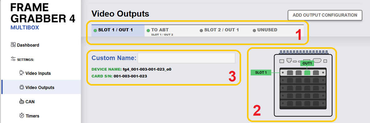
The following section of the page configures timing parameters for the Output device:
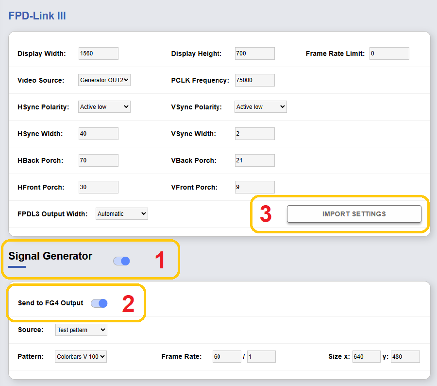
Note: If the Video Source is set to the native Signal Generator ("Generator OUT1" for OUT1 or "Generator OUT2" for OUT2), the GUI automatically enables the "Send to FG4 Output" option.
Other sections or individual settings blocks on the Video Output web page correspond to the Video output configuration as described in the documentation above. They are listed and named here to match the web interface:
By pressing the ADD CAN DEVICE button, a configuration page for the CAN device is added. The FG4 Multibox includes two built-in CAN channels, jcan1 and jcan2. Additional channels can be added, for example, by connecting a external USB CAN device such as P-Can.
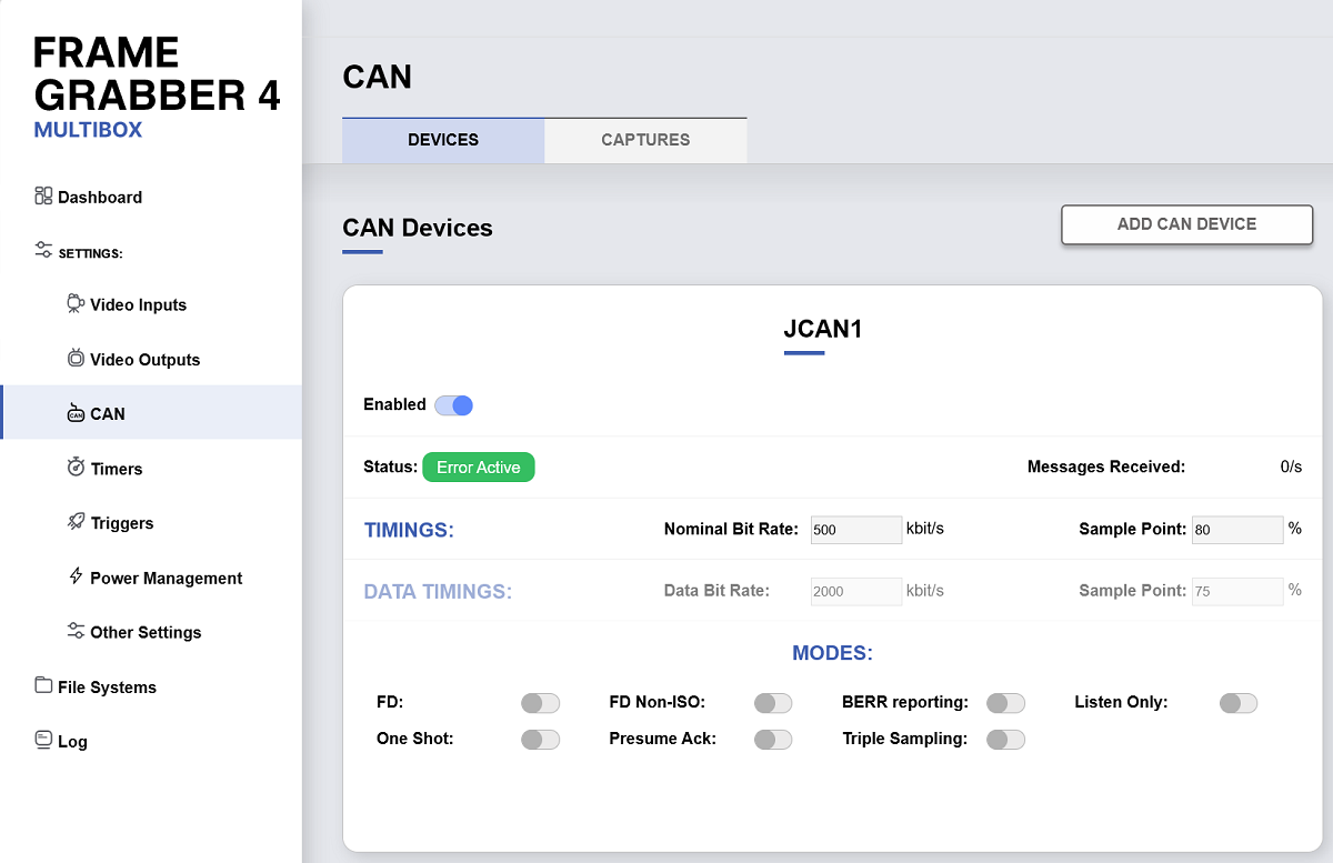
By pressing the ADD CAPTURE button, a CAN Capture is added. The user can then assign it to a CAN Device and configure its filters. By pressing the ADD FILTER button, a Filter is added.
Each CAN Capture includes an Activity Timer function. This function is designed to monitor CAN bus activity. The CAN Activity Timer can trigger a user-defined action when no messages are received through the CAN Capture for a set period, or when the first message arrives after the timer is enabled. This is useful for turning the FG4 Multibox off, for example, after the CAN-bus goes into the sleep mode.
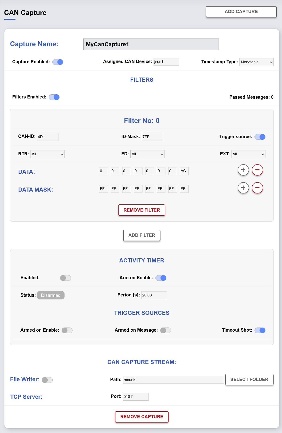
Note: If the CAN-ID and ID-MASK are both set to 0, The RTR, FD, and EXT modes are set to All, and no DATA and DATA MASK is defined, all CAN messages will pass through the filter.